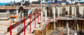
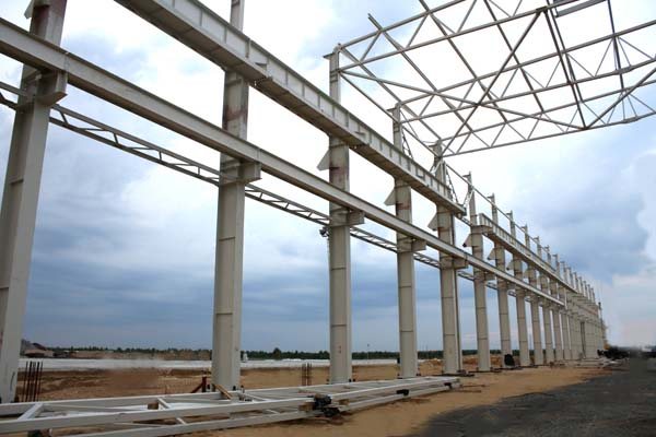
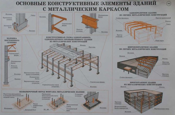
Industrial buildings require high strength and reliability with minimal construction costs, both time and money. Buildings with a steel supporting structure show the greatest efficiency. The quality of construction largely depends on how correctly the installation of metal structures is carried out. Of interest is the installation of columns, crane beams of trusses, half-timbering and flooring.
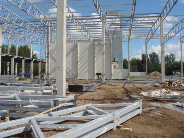
installation of metal structures during the construction of industrial (warehouse) premises
Installation of columns
Most metal columns are placed on a solid concrete foundation. When they are prepared for installation, marks are placed on them indicating the longitudinal axis and the top of the foundation. When installing, the columns are held in one of the following ways:
- Using anchor bolts that are embedded in the foundation. After the column is aligned along two perpendicular axes, the joints are filled with cement mortar.
- Directly with the foundation surface, which is erected to the level of the milled base at the column. In this case, no additional cement mortar is added.
- Using steel support sheets. Their top surface is planed. Pouring cement mortar is carried out if necessary.
To support columns with wide shoes and a height of up to 10 m, it is sufficient to use only anchor bolts. Columns with greater height and narrow shoes must also be supported by braces in the plane where the structural rigidity is minimal.
- The bracing is attached to the top of the column before it is lifted and placed.
- The other end of the braces is attached to anchors or foundation elements located nearby.
- After the braces are fully tensioned, the slings can be removed from the column.
- Complete removal of braces is permitted only after the column is secured with permanent elements. The stability of the column can be ensured by crane beams or ties, which are placed after the installation of the first two columns connected by a crane beam.
When installing columns placed on the foundation, they are secured with anchor bolts during the process. Any metal gaskets placed under the base must be welded. In turn, the columns on the upper tiers are also fastened with bolts or welding. This connection bears a high load, so its strength is carefully calculated during design.

fastening metal columns using anchor bolts
Installation of elements of metal structures using alignment is quite labor-intensive and time-consuming. Therefore, recently an installation method that does not require alignment has been increasingly used. This method allows both to improve the quality of the structure and to reduce the time required for the construction of the building.
Non-alignment installation requires preparation of the metal structure during the manufacturing process and directly on the construction site. To increase the accuracy of the design, the following technological techniques are used:
- Separate production of shoe and base plate;
- Milling the ends of two column branches;
- Planing of base plates;
- The presence of 4 welded strips on the base plate with cut holes for bolt placement;
- Presence of axial marks on column branches.
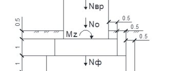
When installation is carried out without alignment, the columns are supported on steel plates. In this option, the foundation is initially concreted below the design value by 50-60 mm, and after installing the slab it is filled with cement mortar.
The base plate is placed using adjusting bolts on the support strips, which are concreted completely flush into the foundation, similar to embedded parts. The supporting surface of the slab is adjusted with nuts so that the difference between the actual elevation and the design position is no more than 1.5 mm.
When a column is being installed, the axial marks marked on the branches are combined with the marks on the base plates. This ensures sufficient placement accuracy, after which the column is secured with anchor bolts. In this case, there is no need to additionally align the column in height or axes. After the braces are installed, crane beams can be mounted on the columns. When the crane beams are aligned along the axial marks with the columns, they do not require additional alignment. After securing the beams, the braces are removed from the columns.
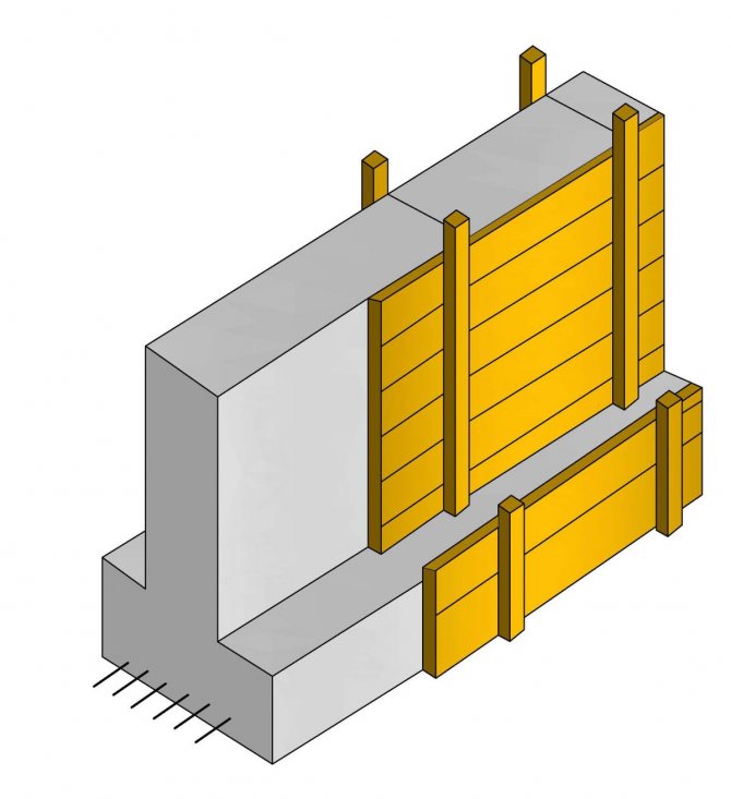
Formwork installation
Before carrying out formwork work, the panels should be assembled. For this:
- a box is made from load-bearing elements (screws);
- shields are attached to fights;
- The edges of the shields are covered with paint marks that show the placement of the axes.
To create formwork for the foundation, produce:
- installation and fastening of panels in the lower part;
- installation of the made box;
- fixing the lower part of the formwork to the base using metal pins;
- placing marks on the bottom box showing the location of subsequent prefabricated elements;
- assembly and installation of the following boxes.
Installation of crane beams
These beams are installed after installing a pair of columns. During lifting, the beam is held in place by two guy wires. To receive it at height, installers are located on scaffolds, platforms and assembly ladders. The workers’ task is to keep the beam from touching the previously installed structural elements and give it the desired position. To control the descent of the beam, there are risks on the console. To eliminate vertical deviation, steel pads are used, placed under the beam. Anchor bolts are used to temporarily secure the beam.
installation of crane beams
If crane beams are installed on columns with milled soles, the foundation of which is concreted to the design value, or columns on planed metal slabs, then it is enough to check the position of the beams along the main axis.
Truss installation
Before installation, the truss must be prepared - assembled, equipped with ladders and braces. Its rotation across the span is carried out using braces. For temporary fastening, braces are also used, as well as spacers, guys and jigs. The truss is verified by axial risks, which are located at the ends.
To lift the trusses, the crossbeams of one or two cranes are used, it depends on the weight and size of the structure being lifted. Their slinging is carried out exclusively in the nodes of the upper chord, otherwise significant bending forces may arise in the rods. Typically, slinging is performed at 4 points using traverses equipped with semi-automatic grips with remote control. If during installation the structural elements experience significant loads, they are reinforced with steel pipes or wooden plates.
The first truss, lifted by a crane, is turned by guys into the required position so that 0.5-0.7 m remains to the top of the columns. The truss is lowered onto the mounting tables located on the columns. Temporary fastening is carried out with bolts, after which its position is verified and the structure is finally attached. To protect against swinging, the truss is held in place by 4 flexible stays during lifting.
Subsequent work on the installation of metal structures of this type is carried out similarly. The second installed truss is connected to the first using purlins, spacers and ties. A rigid spatial structure is formed there. Trusses of adjacent rows are bolted together to increase rigidity.
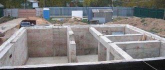
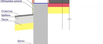
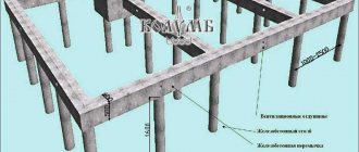
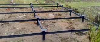
Construction of a columnar grillage foundation
Making a columnar foundation with your own hands for a frame house
If you want to do without specialists (engineers, architects) and start building a house or structure on your own, then you should consider several main aspects:
- grillage type. It depends on the type of soil and the properties of its movement;
- design of the future building. Area, number of floors, building material affect the pressure level;
- location relative to the ground.
Stages of construction of a columnar foundation with a grillage:
Settlement. The theoretical part was presented above.
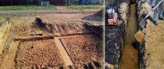
Preparatory. Includes clearing the site of all uneven areas, as well as planning the site according to your project. To check the correctness of the layout, you need to measure the diagonals and angles. Vertical holes for mounting posts can be dug manually or using a drilling rig
It is important not to miss the moment and arrange formwork at a depth of one meter to prevent the soil from collapsing. The width of the hole dug should include the dimensions of the post, formwork and spacers. Installation of formwork
Usually they use wooden boards, less often plywood with moisture-resistant properties, wood boards, and metal sheets.
Reinforcement. It is carried out using a metal rod up to 1.5 cm thick, which are connected to each other with wire in a horizontal position. In order to connect the post to the grillage, it is necessary to provide for the installation of reinforcement in a vertical position above the support at a distance of 1.5 cm.
Pouring with concrete mixture. It is produced in several layers, each of which is 2 cm. Each layer is compacted with a hand-held vibrator.
Waterproofing. This is carried out by laying any waterproofing material inside the formwork.
Installation of the fence. A fence is a wall that covers the empty space under a columnar foundation. It is needed for communications, as well as to avoid the entry of cold air and various precipitation. The best option would be to think through the removal before starting the foundation, since it will be more difficult and inconvenient to do later. Brick can be used as a pick-up material. The intake device includes ventilation and communication openings. The only drawback of the pick-up is its possible settlement under the influence of ground movement.
The final stage is removing the formwork and grouting the ends.
The construction of a columnar foundation with a grillage is an advantageous option for a low-rise building on difficult, swampy and sandy soils, which are characterized by mobility. And the ease and speed of installation does not require the help of special equipment, unlike a slab foundation.
Flooring installation
Industrial buildings with a steel or reinforced concrete frame are often clad with profiled steel decking. This helps reduce the mass of the structure. Profiled panels equipped with insulation show high efficiency. They allow you to significantly save heat, which is quite important in the climatic conditions of our country.
For flooring, stainless steel sheets are used, which are additionally coated with an anti-corrosion compound. Sheets with a length of 3-12 m, a width of 0.86-0.85 m and a thickness of 0.8-1 mm are used. The length of the sheets is usually a multiple of 3 m and is selected during design depending on the location of the truss runs. The standard height of longitudinal corrugations is 60-80 mm.
Before installation, the sheets are connected into cards, since installing the sheets separately is very labor-intensive, given that all work must be carried out at height. Assembly is carried out on horizontal stands, which have corners according to the size of the cards. The sheets are joined using rivets or spot welding. If rivets are used, the holes in the laid out sheets are drilled by hand. The distance between the holes is specified in the project and is usually 50-60 mm. Rivets are placed into the resulting holes, after processing which a single card of the required size is obtained.
Slinging is carried out according to the diagram, depending on the size of the card. The flooring is laid on purlins or floor blocks. The purlins are placed on the nodes of the trusses, and, if the trusses are created from rectangular profiles of a closed structure, then directly on the upper chords of the trusses. Placing cards from profiled sheets is done using marks that mark the place of placement.
For fastening to purlins, equipment for installing metal structures is required, which allows you to quickly connect them to sheets using dowels or electric rivets. The most common fastening is with a nut driver, which is tightened with 6 mm diameter screws with plastic or steel washers under the head.
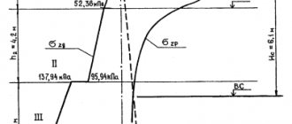
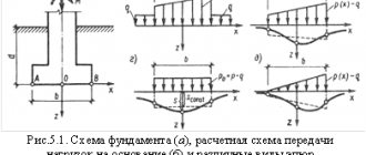
Calculation of the pressure exerted by a building per unit area of soil
Now knowing the mass of the building, you can easily calculate the pressure it exerts. For this, one number is missing - the area of the foundation support.
To calculate the total area of the foundation support, you need to multiply the width of one pillar by the length of this pillar. This way we will find the area of one pillar. Since all the pillars must be the same, to find the total area, you need to multiply the support area of one table by the number of pillars. This way we get the total support area of the entire foundation.
If the pillars are not equal in size to each other, then you need to calculate the support area of each pillar, and then sum them together.
Construction of a columnar foundation
If the pillar has a round rather than rectangular cross-section, then you need to calculate the support area of the round base. This can be done using a simple geometric formula, like the number P = 3.14 multiplied by the radius squared.
At this point the area of support is calculated.
Now, to find the pressure on the ground, you need to divide the entire mass by the total area of the support. It should be taken into account that the mass is best expressed in kilograms, and the support area in square centimeters. Thus, the pressure will have the unit of kilogram per square centimeter.
Comparison of soil resistance coefficient and pressure per unit area of soil
At this stage, you need to compare the results obtained in the first point and in the third. If the soil resistance coefficient turns out to be at least 0.5 greater than the applied pressure, this means that the type of foundation, the number of pillars, and the cross-section of each pillar are chosen correctly. No further modifications to the foundation are required. The construction of the design foundation will be safe.
If the soil resistance coefficient turns out to be less than the applied pressure, then one of two possible measures should be taken:
- Increasing the support area of each pillar. This is achieved by increasing the base of the pillars. You can place a concrete slab under each pillar, which will be larger in area than the area of the base of the pillar. You can simply make the pillar itself longer and wider;
- Increasing the number of pillars. Additional supports in the form of pillars must be placed on straight sections. However, this method is difficult to implement, since you need to try to place the pillars symmetrically throughout the house under construction; if this is not observed, then the possibility of uneven subsidence of the house arises.
After taking such measures, the calculation should be made again, and again, based on its results, appropriate conclusions should be drawn.
Connecting metal structures by welding
Most of the installation connections are made by welding, a smaller part by bolts, and rivets are used even less often. This affects the cost of installing metal structures - welded joints are the cheapest. Connecting with rivets is the most labor-intensive, however, in some cases it is necessary to use only it. An example would be the building of a forging and press shop, in which bolts or welding cannot be used to create a load-bearing metal structure—the constant vibration created by the forging equipment will inevitably destroy these connections.
Welding is used when a rigid connection of structures is required, with a tight fit of the element and a water- and gas-tight seam. This is the only way to connect sheet structures in the casings of blast furnaces and thermal furnaces, tanks, dust collectors and gas holders. Among supporting structures, welded joints are used for the joints of columns with crane beams and trusses. Elements of steel structures can be welded with reinforced concrete elements. In such cases, the profiles are welded to the embedded parts.
To obtain a high-quality seam, the parts to be welded are pressed tightly against each other. Basically, rough mounting bolts are used for this. In some cases, additional metal joining plates are used to create a connection.
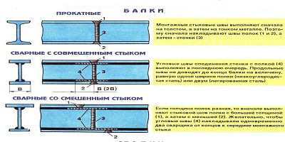
Columns whose height exceeds 18 m are divided into shipping elements for transportation, the dimensions of which depend on the means used for transportation. For installation, parts of the columns are assembled into a single whole. Column joints during the construction of one-story industrial buildings are usually made in the part above the crane, above the crane beams. The milled ends of the main and crane parts of the columns are joined and welded along the contour of the joint. To increase the rigidity of the connection, butt sheet overlays are used.
To install crane beams, they are supported on the corresponding column slabs and connected first with bolts and then welded. Additional fastening of the beam is carried out to the crane part of the column using brake structures. They are also initially bolted and welded with an extended seam. The connection of trusses with columns is carried out in a similar way.
When installing buildings made of metal structures, the quality of the welds performed is of great importance. They are checked by external inspection, which can determine deviations from geometric dimensions, cuts, lack of penetration or large pores. The surface of the weld should be smooth or have small flakes, and the deposited material should be of the same density. The permissible sizes of deviations and defects are specified in regulatory documents.
Connecting metal structures with bolts
Bolted connections can be made with bolts of varying accuracy depending on the purpose of the connection and the loads it can bear. Fasteners of normal and high accuracy are mainly used. For connections that are subject to shear loads, normal and rough precision bolts must not be used.
Holes for bolts are drilled or pressed so that the diameter of the hole exceeds the outer diameter of the bolt by 2-3 mm. This simplifies assembly, but makes them less resistant to deformation. For this reason, bolts classified as coarse and normal in accuracy class are used only when one element directly rests on another. Examples include connections on support tables, strips and flanges.
Connections that use high-precision bolts are an alternative to rivet connections in hard-to-reach areas. For such connections, the diameter of the holes is larger than the diameter of the bolt by up to 0.3 mm. If this requirement is met, the bolts sit in the holes very tightly and withstand shear loads well.
High strength bolts are the most effective fasteners. They combine high load-bearing capacity with significant resistance to deformation. Such bolts can be used instead of rivets in almost all connections. The nuts for such bolts are tightened using ratchet wrenches, which allows you to control the tightening force.