Calculation of the foundation for a mast for overturning and shifting?
| Page 1 of 5 | 1 | 2 | 3 | > | 5 » |
Hello, forum users!
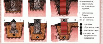
It is necessary to calculate and design the foundation for a 25m high lighting mast as soon as possible. Seismic 8 points. The mast itself weighs 1.4t plus perhaps another 0.5t (the lifting capacity of the mechanical drive on it). Wind region – IV. The standard mast is MF-25-M(500)-IV-6-ts, shown in the screenshot. Here, for example: https://www.mos-opora.ru/produktsiya/. bilnoy-koronoy presents a table with the foundation, where it is written “25+2”, i.e. The height of the foundation should be at least 2 m, since the “anchor embedded element” is typical (shown in the figure at the link). At first I planned to use a regular columnar foundation (see attached file), because... the vertical load is small. However, there are two BUTs that confuse me very much: 1) Will this foundation capsize?! 2) The bulk soils are compacted and reach from 4 to 5 m (closer to 4 m in this place). Accordingly, several questions arise: 1) Is it possible in this case to rely on bulk soil or not? Previously, I always tried to go through bulk soils and did not support anything on them. 2) Help me calculate the foundation for overturning and shifting? The calculated value of the soil for this foundation resting on bulk soil turned out to be R = 600 kPa. Judging by the deformation modulus, then E = 25 MPa - for bulk soil, for the next gravel - E = 19 MPa, for the 3rd wood soil - E = 25 MPa, for the 4th marl - 300 MPa. Those. It turns out that if the foundation is still a columnar foundation, then does it make sense to rest it on the 2nd or 3rd layers of soil? Let me remind you that the thickness of the bulk soil is 4 m. 3) You can, of course, use a columnar foundation on a pile foundation. However, you still need to fit a 2-meter “anchor embedded element” somewhere. What to do then in this case?
PS! I’m friends with Lyra, if there are Lyra people. PPS! Everything, as always, was given only today, but it should have been handed in yesterday. *** Thanks in advance to everyone who responded!
| 06.12.2012, 16:03 | #1 |
| DWG 2010 | Columnar foundation.dwg (85.0 Kb, ) |
| Ivan3891 |
| View profile |
| Find more posts by Ivan3891 |
06.12.2012, 16:28
| #2 |
1) No. 2) R=60tn/m2 for bulk soil is terribly too much (look for an error), when calculating it is necessary to check P 0.25; Pmin>0. In the case of a trapezoidal pressure figure under the sole, tipping is excluded. It is better to rely on IGE2 and beyond. It is not rational to use piles up to 4 meters inclusive (the book was about the rational use of pile foundations). Shift in your case is hardly possible; the wind is counteracted by the backfill soil + the mass of the foundation + friction along the base. 3) Make the grillage higher (h).
P/S. In your case, the most labor-intensive process is to determine the force arising from the mast, since it is necessary to take into account wind pulsation and seismicity, and without calculation programs it is extremely problematic to do this.
| Sacha 63 |
| View profile |
| Find more posts by Sacha 63 |
06.12.2012, 16:37
| #3 |
| slava217 |
| View profile |
| Find more posts by slava217 |
06.12.2012, 16:41
| #4 |
| Ivan3891 |
| View profile |
| Find more posts by Ivan3891 |
06.12.2012, 16:55
| #5 |
| Sacha 63 |
| View profile |
| Find more posts by Sacha 63 |
06.12.2012, 17:28
To bear the load, a size of 2.4x2.4 is not enough for your mast - tearing off the base of the foundation.
With a depth of 2.4, a base size of 4.2x4.2 is required to meet the requirement Pmin/Pmax > 0.25 With a depth of 2.4, a base size of 3.3x3.3 is required to meet the requirement of Pmin > 0
The reinforcement of the head is also insufficient.
Calculated for loads at N=2.1t
Dimensions are given without taking into account seismic shear checks of the foundation.
06.12.2012, 17:42
Justify with documentation that it is impossible to build on fill soils, or is this again purely your personal opinion, which you do not impose on anyone?
And what. The masts are factory-made, already designed for certain wind loads, with maximum forces applied to the foundation.
Are you reading the topic, comrades? I just want to know (remember) how to calculate the foundation for overturning and shifting. Why did I get this mast, which the customer, knowing the brand, will order and install. I have all the effort. Seismicity and wind are not considered at the same time! – that’s what Lyra technical support told me a long time ago, when I started. And in this case, the load from the wind will be greater, which must be considered in geometric nonlinearity. In my case, it is typical for a certain wind region and has already been calculated before production. So I don't really care about the mast. I just need to develop the foundation.
To bear the load, a size of 2.4x2.4 is not enough for your mast - tearing off the base of the foundation.
With a depth of 2.4, a base size of 4.2x4.2 is required to meet the requirement Pmin/Pmax > 0.25 With a depth of 2.4, a base size of 3.3x3.3 is required to meet the requirement of Pmin > 0
The reinforcement of the head is also insufficient.
Calculated for loads at N=2.1t
Dimensions are given without taking into account seismic shear checks of the foundation.
| #6 |
| #7 |
| Ivan3891 |
| View profile |
| Find more posts by Ivan3891 |
06.12.2012, 17:50
| #8 |
| Geter |
| View profile |
| Find more posts by Geter |
06.12.2012, 17:53
| #9 |
| Ivan3891 |
| View profile |
| Find more posts by Ivan3891 |
06.12.2012, 18:23
| #10 |
| Sacha 63 |
| View profile |
| Find more posts by Sacha 63 |
06.12.2012, 19:11
Attachments
| #11 |
| columnar.zip (115.5 Kb, ) |
06.12.2012, 19:52
| #12 |
| Igor V |
| View profile |
| Find more posts by Igor V |
07.12.2012, 12:20
Firstly, geologists have indicated everything that is needed! See attached file “geology.jpg”. Secondly, SNiP 2.02.01-83 is no longer in force, but its updated version SP 22.13330.2011 is now in force. Well, God bless him, the new one, as a rule, complements the old one and largely repeats it. Thirdly, I can read, and you? Read carefully what paragraph 2.42 says: “Preliminary dimensions of foundations are assigned for structural reasons or
based on the tabulated values of the calculated resistance of foundation soils R(0) in accordance with the recommended Appendix 3″.
And where does it say that you can’t build on fill soils? Fourthly, I read the “Technical Regulations on the Safety of Buildings and Structures” as soon as it appeared. And I don’t remember anything about a ban on construction on fill soils. And you? Fifthly, you write from the same paragraph 2.42: “the final dimensions of the foundation according to R0 can only
for buildings and structures of class III responsibility.”
This is not entirely true! The continuation of paragraph 2.42 reads verbatim as follows: “Values R(0) may also
be used for the final determination of the dimensions of foundations of buildings
and
structures of class III, if the foundation is composed of horizontal (slope no more than 0.1), consistent in thickness layers of soil, the compressibility of which does not increase within a depth equal to twice the width of the largest foundation, counting from its base.”
And where is the adverb “only” here? Perhaps you meant clause 2.13(2.5) of the Manual for that same SNiP 2.02.1-83*, which says the following: “Loads on the foundation can be determined without taking into account their redistribution
by the superstructure when calculating: a) the foundations of buildings and structures of class III ; . For me, all the foundation work is given by the mast manufacturer in their table (check out one of the first screenshots of the mast), so let's forget about the mast and focus on the foundation!
Thanks for your calculation. I want to ask you, in which program did you consider my foundation to be taken off?
Now, with the help of a friend, I carried out my manual calculation of a columnar foundation for separation with dimensions of 3.3 x 3.3 m along the base and a height of 3 m. It doesn't work either. (((As I understand it, the relative eccentricity should be less than 1/6 (0.167), right? Is it possible to make the relative eccentricity at least 0.25 for masts or not?
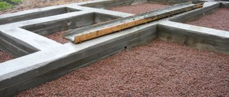
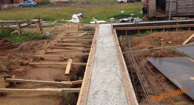
Pouring concrete
Having completed the preparatory activities, we move on to the main stage - concreting. By the way, it is proposed to consider the second method of reinforcing the sole.
After pouring concrete into the formwork, we lay out reinforcing bars in two even rows, moving them fifteen centimeters away from the formwork walls. We push the reinforcement under the partition elements from the fastening brackets. Having finished the layout, we “drown” the metal twenty centimeters into the concrete mixture with a bayonet shovel, and carefully perform “bayoneting” to eliminate the air remaining inside the concrete.
As soon as the surface of the concrete rises to the nails driven into the upper edge of the future sole, the U-shaped brackets are raised by five to seven centimeters.
Two operations remain - constructing the sole and grouting its surface. The first stage is considered important and responsible; the keyway must be cut with special attention. This work is performed from above, along the central axis of the edge. The keyway will help ensure the strength and quality of adhesion between the sole and the foundation wall.
Work on constructing the groove begins when the poured concrete solution has hardened a little.
To work, you will need a small block that is pressed evenly along a straight section of the foundation sole.
The formwork system is carefully dismantled, all marks made on its panels are transferred to make it more convenient to erect foundation walls.
Now it is extremely clear what is meant by the name “base of the foundation.” It remains to consider the advantages and disadvantages of the design.
It is believed that a strip foundation on a sole is erected in any weather conditions, including in winter. Such a base is considered universal, suitable for the construction of load-bearing walls made of brick or stone materials, concrete, and wood.
As a disadvantage, many note the complex technological process of arranging the foundation base.
It should be noted that the sole is poured under the FBS blocks, and when installing a pile foundation, the supporting soles are placed in ten to fifteen places (according to the number of supporting elements).
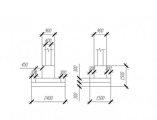
Calculation of a columnar foundation for overturning
The design diagram is shown in Figure 2.4
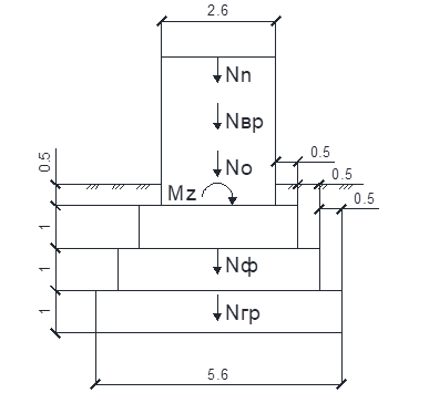
Figure 2.4 – Scheme for calculating the rollover test
In order for the foundation not to tip over, the following conditions must be met:
Where ; – coefficients, respectively, operating conditions and reliability for the intended purpose;
– moment of overturning forces;
– moment of holding forces, according to formula (2.19)
Under normal operating conditions and the construction of foundations in accordance with the norm, its overturning is not possible.
Checking for flat shear on the sole
The design diagram is shown in Figure 2.5
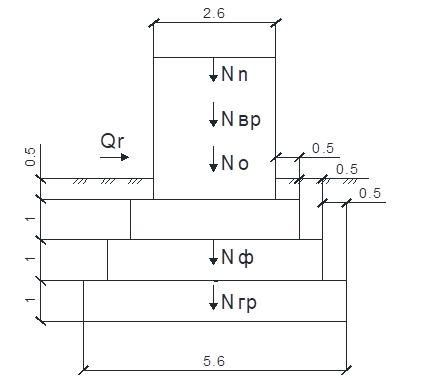
Figure 2.5 – Scheme for calculating the test for flat shear along the sole
To ensure that there is no flat shift of the foundation along the base, the following conditions must be met:
Where ; – coefficients, respectively, operating conditions and reliability for the intended purpose;
– shear force, according to formula (2.21);
– holding force, according to formula (2.22).
where is the friction coefficient of the foundation on the ground
There will be no flat shift along the base of the foundation
.
Checking for foundation buckling
The design diagram is shown in Figure 2.6
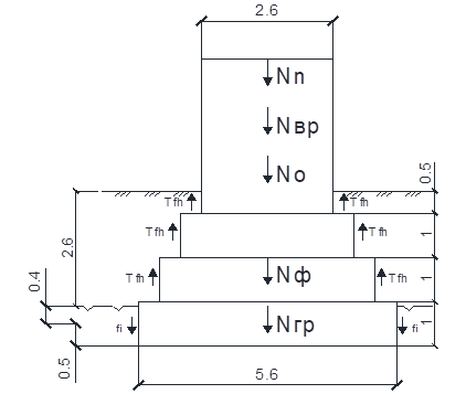
Figure 2.6 – Scheme for calculating the foundation buckling test
where is the calculated specific tangential heaving force;
– area of the lateral surface of the foundation within the estimated freezing depth;
; – coefficients, respectively, operating conditions and reliability for the intended purpose
– the calculated value of the force that keeps the foundation from buckling due to friction of its side surface with thawed soil lying below the freezing depth, according to formula (2.24).
where is the perimeter of the foundation section within the thawed soil;
– design resistance of the i-th soil layer;
– thickness of the i-th layer of thawed soil.
Conclusion: the foundation is stable.
Materials and tools needed for work
As a rule, to fill the foundation base under a strip structure you need:
- bayonet and shovel shovels for excavation work;
- reinforcing bars and binding wire;
- hammer;
- hook for tying a metal frame;
- nails;
- marking cord (preferably two);
- level;
- poles;
- lumber with cross-sectional dimensions of 5 by 30 cm;
- concrete solution;
- mounting brackets.
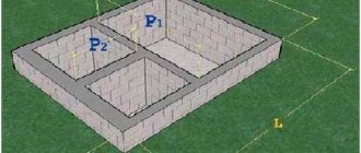
How to calculate a columnar foundation?
A columnar type foundation is a concrete or metal frame (grillage) supported by vertical pillars buried in the ground to a certain depth.
The material for constructing the pillars can be reinforced concrete, solid clay brick, blocks, metal pipes or rubble stone. A wider footing may be provided at the bottom of each support column to increase the support area. The cross-section of the vertical supports can be round or square.
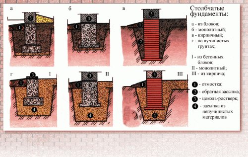
Options for columnar bases.
The reliability of the foundation structure largely depends on the calculation of the columnar foundation and the correct location of the support pillars that must be installed:
- from all corners of the building;
- at the junction and intersection of walls;
- on straight sections of the grillage no further than two meters from each other.
The structure of the grillage frame should serve as a support for all load-bearing walls and partitions. If the building is long, additional transverse jumpers should be provided to ensure a more reliable connection between the longitudinal beams.
Device Features
As world construction practice shows, the strength of the foundation increases due to the width of its reinforced concrete base.
An important condition is the location of the sole below the freezing level of the soil composition.
This feature is observed in order to prevent damage to the building due to ground movements.
In order to determine the parameters of the foundation with maximum accuracy, certain factors are taken into account, which include:
- type and condition of soil composition;
- project of the building planned for construction;
- brand of concrete mixture;
- percentage of reinforcement for reinforcement.
Construction work of any structure begins with the construction of the foundation, and it is very important to realize the responsibility and importance of correctly carried out calculations. It is best to entrust such work to experienced specialists to avoid further troubles.
Requirements for the use of columnar bases
The low cost of a structure supported by vertical pillars makes it very attractive to private developers. However, this type of foundation has a number of limitations on its use.
Unfavorable conditions for the use of columnar bases include:
- probability of horizontal soil mobility and lateral external loads;
- soil prone to subsidence or heaving;
- high groundwater level, which should not come closer than 500 mm to the base;
- soil freezing depth more than 1.5 m;
- height differences on the building site are more than 2 meters;
The reduced load-bearing capacity allows it to be used only for frame houses, the construction of light residential buildings from panel and wooden materials, as well as small bathhouses, verandas, extensions, utility buildings and for a frame garage.
The specific weight of wall material for one-story buildings should not exceed 1000 kg/m 3, and the thickness of the walls should not be less than 400 mm. The use of heavy reinforced concrete floors, beams and lintels is not permitted.
For rooms such as verandas, extensions and outbuildings, it is recommended to make your own foundation. The weight of their structures is much less than the residential building itself. Therefore, a simpler and cheaper design can be used. In addition, such a separation can significantly reduce the total area of the house and lead to different design results.
Adjustment of calculations
If the load transmitted through the foundation exceeds the soil resistance, you can act in two ways:
- The first is to replace the materials for building a house with lighter ones. This is an irrational path: it takes a lot of time to redo the project and all the calculations.
- The second option is to reduce the specific load by increasing the thickness of the foundation tape.
It is worth noting that if the width of the tape is more than 60 cm, especially with a large depth, then the work becomes unprofitable. In this case, you will have to compare several types of foundations by cost.
Of course, changing the width of the tape requires recalculating its weight and correspondingly adjusting the total weight of the building.
Initial data for the calculation
In order to correctly calculate the number of supports for a columnar foundation, you need to have information. Such initial data for calculation include:
- a report on geotechnical surveys, including the structure of cross-sections of the soil and data on the occurrence of groundwater;
- soil bearing capacity;
- freezing depth and amount of snow cover in a given area, taken from SP 131.13330.2012 “Building climatology”;
- data on the specific gravity of building structures from which the building will be constructed, taken from SP 20.13330.2016 “Loads and impacts”.
If you decide not to involve specialists to carry out survey work, and you do not have information about the geology of the site, then you will need to study the soil yourself.
To do this, it is necessary to dig 2-3 holes at the building site to a depth of at least 0.5 meters below the foundation support pad. If a moisture-containing layer is discovered, then a columnar foundation cannot be used for construction. You'll have to choose a more expensive base.

Determining the type of soil with your own hands.
Assessment of soil bearing capacity
The natural composition of the soil determines its bearing capacity and therefore, after studying the geological data, it is necessary to select from the table. 1-5 on page 6 SNiP 2.02.01-83 “Foundations of buildings and structures” data on the calculated resistance of soils corresponding to the real situation. It should be taken into account that the given numerical values refer to a depth of more than 1.5 meters. Every 500 mm rise increases this value by 1.4 times.
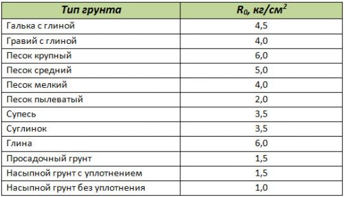
Soil resistance table (R).
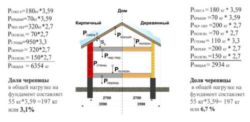
Determination of weight loads on the foundation base
The weight of building structures, snow cover in winter, engineering equipment and household equipment is the most important determining factor for calculating the foundation. You can try to calculate each individual structure based on the specific gravity of its constituent elements, but this is a very large and complex task. The reference literature already provides average generalized data that can be taken as a basis. Here are some of them:
- wall made of timber with a thickness of 150 mm - 120 kg/m2;
- log walls 240 mm – 135 kg/m2;
- frame walls with insulation 150 mm thick - 50 kg/m2;
- foam concrete blocks of grade D600300 mm – 180 kg/m2;
- interfloor ceiling on wooden beams with insulation - 100 kg/m2;
- the same attic floor including insulation - 150 kg/m2;
- concrete hollow slabs - 350 kg/m2;
- operational load of floors – 200 kg/m2;
- roofing covered with metal tiles - 30 kg/m2;
- roof with slate – 50 kg/m2;
- roofing with ceramic tiles – 80 kg/m2;
- snow load for central Russia – 100 kg/m2;
- for southern regions – kg/m2.
When making calculations, you should also take into account the mass of the foundation itself. To do this, determine its volume and multiply it by the average specific gravity of reinforced concrete - 2500 kg/m2. The pitched roof angle may decrease or increase the value shown here as it changes.

Weight of building structures.
Installation of formwork
We continue to understand how the strip foundation is installed on the sole.
The installation of the poles is completed, all that remains is to build the formwork. To do this, you should use lumber whose cross-sectional dimensions are 50 by 300 mm, connecting it with metal brackets in the shape of the letter “P” that hold the formwork panels outside and inside the structure. The optimal interval for their installation is about fifteen centimeters.
The formwork is placed in such a way that the foundation walls are distributed in the center of the base. After this, a pair of boards are connected at right angles, which are removed from the marking cord at a distance of 17.5 cm. Such actions are necessary to form the outer corners.
Having completed this activity, we install and fix the boards under the internal formwork wall. Fastening brackets are placed on each side of the joining area of the boards.
If the boards are not joined too tightly, the detachable areas are sealed with overhead boards stuffed from the outside. The long ends are placed on the adjacent board and overlapped.
Formwork boards should be leveled and adjusted, since this factor has a direct impact on the strength of the element being installed and on the ability to perform its intended functions.
Having completed the installation of the formwork, its weakest areas are partially covered with a soil composition. As a rule, this precaution is necessary in connecting areas or in places where fasteners are missing. Adding sand will prevent concrete mortar from leaking under the formwork boards.
The final stage is the installation of the upper level of the edge of the foundation base. This marking must be done using a theodolite. To clarify the level, fasteners are made with small nails driven to half the length in increments of one meter. These guidelines will help you pour the concrete solution evenly.
General calculation of a columnar foundation
The calculation of the foundation structure is based on determining the total cross-sectional area of all supporting pillars of the foundation (S). It is defined as the ratio of the total mass of the building (P) to the calculated soil resistance (Ro) according to the formula:
S = 1.4 x P/Ro , where 1.4 is the safety factor.
When drawing up a preliminary layout of the foundation pillars, their arrangement and the minimum possible number were determined. Therefore, by dividing the total cross-sectional area by the number of supports, you can obtain the cross-sectional dimensions of each individual columnar foundation for the column.
If the size of the columns is less than 400 mm, then this minimum size should be accepted. If the required cross-section of the pillars is more than 600 mm, it is necessary to increase their number in the diagram, changing the distances between the supports on straight sections so that the weight load is distributed more evenly.
The minimum area of the support cushion must exceed the cross-section of the pillar by one and a half times with a thickness of 400 mm.
The base of the pillar is made of reinforced concrete in formwork with mandatory double-row reinforcement and an underlying layer of crushed stone at least 100 mm thick.
The supporting plane of the lower part of the support should be 30-40 cm deeper than the freezing level of the soil.
Calculation of loads
Now we divide the total mass of the building by the expression of the area of the foundation in order to calculate the force with which the building will press on the foundation.
We multiply the length of the foundation strip by the width determined in the previous section and obtain the value of the area of the strip foundation. Next, we divide the total load by the area of the base, expressed in square centimeters, and find out the specific load acting on one square centimeter of the foundation.
Example:
Building load – 408,000 kg;
The area of the foundation strip is 132,000 cm2 (width – 30 cm, length – 4400 cm).
408000 kg / 132000 cm2 = 3.09 kg.
The soil has the ability to withstand some load. The calculated values of these loads, determined as a result of geological studies, are included in the table presented.

We select the type of soil on a conditional construction site and see how its calculated resistance corresponds to the specific load we calculated. The soil resistance value should be slightly greater than the specific load figure, otherwise the calculations must be adjusted.
Example of calculating the number of pillars
The task is to calculate the foundation for a small frame house in the middle climatic zone of Russia, measuring 5 x 6 meters with a floor height of 3.0 meters and a metal tile roof. An example of calculating a columnar foundation includes several points.
- we use a foundation on round reinforced concrete pillars as a support;
- the main soil at the building site is loam (Ro – 3.5 kg/cm2);
- freezing depth 1.1 meters;
- When drilling the control pit, no groundwater was found.
Determination of weight load:
- the total area of the external walls and partitions is 76 m2 and then their total weight will be 76 x 50 = 3800 kg;
- the mass of the basement floor with an area of 30 m2 is 30 x 100 = 6000 kg, and the weight of the attic floor is 9000 kg;
- the roof area is 52 m2, which means that such a roof weighs 30 x 52 = 1560 kg;
- the snow load will be 20% of the standard with a slope of 46˚, which will be 100 x 52 x 0.2 = 1040 kg;
- the operating load on one floor is 30 x 210 = 6300 kg;
- to estimate the mass of the foundation, we take the number of pillars from a pre-compiled diagram and take their diameter to be 400 mm, then the mass of 10 pillars 1.5 meters high will be 540 kg;
- the weight of the grillage is the mass of reinforced concrete beams with a section of 400x400 m, which will be equal to 980 kg.
Conditional weight of a wooden and brick house.
Summing up the data obtained, we obtain the total weight of the house equal to 29110 kg. To determine the total cross-sectional area of the pillars, we divide 29110/3.5 = 8317 cm 2.
Then the cross-sectional area of each of the 10 pillars will be equal to 832 mm 2, which corresponds to a diameter of 326 mm. We take the diameter to be 400 mm and determine that for this building the minimum number of pillars required is 9 pieces.
However, taking into account the need for a strength margin of 40%, 13 pillars with a diameter of 400 mm should be accepted for installation.
Features of the technology
The base of a monolithic strip foundation is a reinforced concrete platform. Its task is to distribute the load evenly. The width should be at least twice the width of the base itself. Height - about 30cm. In the traditional version, the sole is reinforced with steel reinforcing bars.
The technology consists of several stages. First, mark the bottom of the pit for the foundation of the house. The poles are installed, then the formwork is constructed. Most often, boards are used, connected by steel brackets sunk into the ground. The formwork is installed so that the walls are located in the center of the base. The boards are usually not trimmed; the gaps are sealed with short overhead boards, nailing them from the outside.
The next stage is partial backfilling of soil near potential problem points. The event helps the concrete pass under the formwork, lifting it up. Next, the level of the top of the sole of the strip foundation is established. The edge must be located horizontally, at a given depth. The marks are fixed with small nails.
It's time for concrete. They begin laying it in areas inaccessible to a concrete truck. Then comes the turn of reinforcement with steel rods. The final stage of sole construction is cutting a keyway along the center line along the top edge.
With careful adherence to technology, the strip foundation with a sole turns out to be strong and durable. It will ensure trouble-free operation of the building for many years. provides construction services in the Moscow region and Moscow at a professional level.
Calculation of a columnar foundation for overturning
Conclusion: the stability of the structure is ensured
Calculation of advertising structures using the APM WinMachine software package
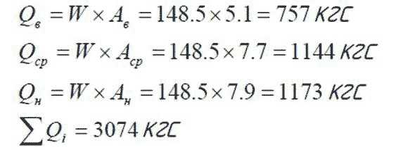
The calculation of the superstructure (transverse beams and cap) was performed using the automated calculation system APM WinMachine of the APM Structure3D module, designed for calculating the stress-strain state of rod, plate, shell and solid structures, as well as their combinations. Depending on the wind installation area and the height of the structure, there are two options for the design of the transverse beams (a bent channel 236x70 and a channel with reinforcement from the same section, 2 m long) and the head (pipe 160x160x8 (C245) and 160x160x8 (C345)) (see Table 1 ) The elements are checked for each of the design options, and the case is considered in which the sum of bending moments for an element of a given section is the greatest. Checking the strength of transverse beams made of bent channel 236x70 without reinforcement. Design diagram (according to Table 1 and Table. 2) is accepted for the IV wind region, the height of the stand is 4 m, while the load on the transverse beams (respectively on the upper, middle and lower) will be:
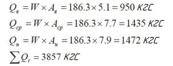
Checking the strength of the section of the head made of pipe 160x160x8 (C245) The design scheme (according to Table 1 and Table 2) is accepted for the IV wind region, the height of the stand is 4.5 m, and the load on the transverse beams will be:
The linear load on the beams is:
Checking the strength of the cross-section of the head, made of pipe 160x160x8 (C345) and cross-beams made of bent channel with reinforcement. The design scheme (according to Table 1 and Table 2) is accepted for the V-th wind region, the height of the stand is 45 m, with the load on the cross-beams will be:
The linear load on the beams is:
The calculation results are given in the appendix to the calculation (corresponding to Appendix 2, 3) Conclusion: the presented calculation showed that the load-bearing elements of the structure meet the strength requirements, the maximum equivalent stresses do not exceed the permissible ones .
Calculation of the bolted connection of the head (advertising field) of the structure
Checking the cross-section of M24 bolts (Cl 8.8):
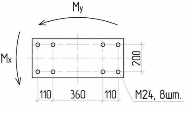
– force in one bolt due to torque relative to the X-X axis
– force in one bolt due to the moment relative to the YY axis:
Total for the most loaded bolt is P = px+py=6197 + 1755 = 7952 kg The load-bearing capacity of the M24 bolt will be: Nb = Rbt ×Ab = 4000 × 3.52 = 14080 kg, where Rbt is the design tensile strength of the bolts (Cl 8.8) Abn is the cross-sectional area bolt net Total: P = 7952 List of used literature
1. SNiP 2.01.07-85* “Loads and impacts” 2. SNiP II-23-81* “Steel structures” 3. Umansky A. A . "Designer's Handbook", Moscow 1960. 4. Rabotnov Yu. N. “Strength of materials” 5. SNiP 23-01-99 “Building climatology” 6. SNiP 2.0311-85 “Protection of building structures from corrosion”
* As an example, the calculations of advertising structures by one of the leading outdoor advertising operators operating in Russia are shown. ** SNiPs used in calculations of advertising structures
Moscow 2008
1 part. Wind load