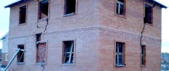
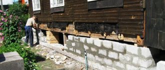
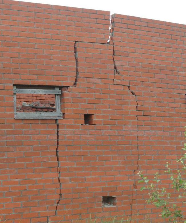
What is land subsidence
Subsidence is sometimes confused with settlement. Meanwhile, these are completely different phenomena. Settlement is the vertical displacement of soil that occurs as a result of its compaction under the influence of load. Soil subsidence is its ability to decrease in volume under its own weight when wetted. Similar processes can occur during thawing of frozen soil, as well as seismic or vibration effects on it.
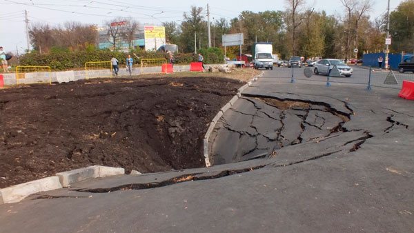
Land subsidence can be dangerous to human life and health
Physical and mechanical properties of soils
Physicochemical characteristics
Plasticity of soils
Indicators:
Upper plastic limit WL
-humidity, above which the soil begins to flow;
Lower plastic limit WP
-humidity between semi-solid and plastic state.;
Plasticity number IP
=
WL-WP
;
Flow rate IT = (W-WP)/(IP).
Definition:
Lower plastic limit
– Humidity at which, when rolling into a cord with a diameter of 2 mm, the soil is rolled out into a cord;
Upper plastic limit
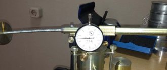
– definition using the Vasiliev cone
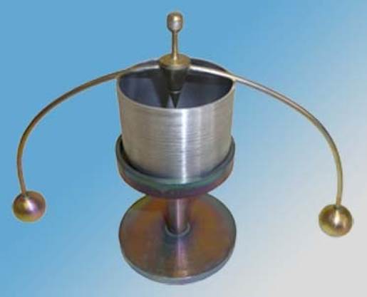
Balance cone for determining the upper plastic limit
Soil swelling
Indicators:
Relative swelling εst –
the ratio of the increase in the height of the soil sample after free swelling under conditions of impossibility of lateral expansion
(h-h0)
to the initial height of the sample
h0
at natural humidity.
εst =(h-h0)/h0;
Swelling moisture
– humidity at which maximum free swelling is observed;
Swelling pressure
– pressure that develops during swelling.
Definition:
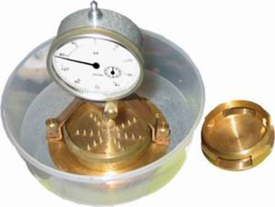
Device for determining the free swelling of soil
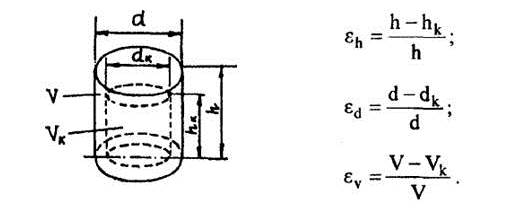
Shrinkability (shrinkage) of soils
Indicators:
Soil shrinkage
is called a decrease in its volume as a result of the removal of water during drying or under the influence of physicochemical processes (osmosis).
Linear shrinkage
– reduction in the linear dimensions of the sample as a result of shrinkage
ΔL=(d-d1)/ d
, where
d and d1 are
the initial and final linear dimensions of the sample, respectively;
Volumetric shrinkage
— reduction in the volumetric dimensions of the sample as a result of shrinkage
ΔV=(V-V1)/ V
, where
V and V1
are the initial and final volumetric dimensions of the sample, respectively;
Humidity limit of shrinkage Wpu
- this is the humidity value at which shrinkage stops. Calculated as the value of weight moisture.
Definition:
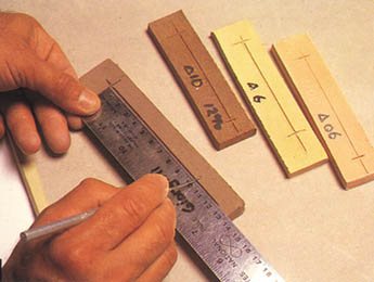
Determination of linear soil shrinkage
Determination of volumetric soil shrinkage
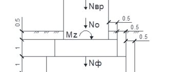
Physical and mechanical properties of soils
Deformation properties behavior of soil under load until failure
Compression
Compression
– compression without the possibility of lateral expansion.
Indicators:
Compaction factor
– the ratio of the change in the porosity coefficient to the difference in stress that caused these changes:
a =Δε/Δσ.
The compaction coefficient is measured in MPa-1.
Compressive deformation modulus Ek
is a quantitative characteristic of soil compressibility during compression tests and the reciprocal of the compaction coefficient:
Ek
=
1/a = Δσ/Δε,
MPa.
Total strain modulus
or
simply the deformation modulus E
characterizes the deformation behavior of the soil under conditions of the possibility of lateral expansion in the presence of elastic and residual deformations.
In the practice of engineering-geological research, the deformation modulus is calculated using the formula: E = β(1+ε0)/a, where β is
the factor for the transition from compression (without the possibility of lateral expansion) during compression tests to compression that occurs in nature; numerically it is taken equal to 0.8 for sands; for sandy loam 0.7; for loams 0.5; for clays 0.4.
Settlement module ep
– the magnitude of direct vertical compression of a column of soil 1 m high when an additional load is applied to it
σ = 0.3 MPa
(Maslov N.N.).
e
=
1000 Δh/h
millimeters per meter.
Definition:
N.N. Maslov’s device for compression testing of soils
Calculation procedure
1. Using Table 2.10, calculate the values of soil skeleton density and porosity coefficient ε0
for your option;
2. Using table 2.11, calculate the porosity coefficient values for each specific load using the formula: εi = ε0 - Δh(1+ε0)/h;
3. Plot the dependence of the porosity coefficient on the load ε=f(σ)
;
4. From the graph, for the section of the greatest slope of the curve in the corresponding load interval, determine the compaction coefficient;
5. All other indicators should be determined based on previous calculations, taking into account the characteristics of the soil (Table 2.10).
Subsidence (subsidence) of soils
Subsidence
– sharp deformation (decrease in volume) of the soil when moistened
.
The concept applies only to loess. Indicators:
Relative subsidence δpr
– represents the ratio of the change in the thickness of the soil layer (height of the sample) as a result of soaking at a given vertical pressure to its thickness in natural occurrence (height of the sample at natural pressure). Relative subsidence is determined by the formula:
δpr =(h′-hpr)/ h0
,
where h′-
– height of a soil sample of natural moisture, compressed without the possibility of lateral expansion at test pressure,
hpr
– height of the same sample after soaking it until complete water saturation while maintaining the soaking pressure,
h0
– 10 mm.
Macroporosity
characterized by the difference in porosity values before and after subsidence as a result of wetting under load.
To calculate macroporosity, calculate the values of the porosity coefficient using the formula: ε = ε0
-
Δh(1+ε0)/h
before and after subsidence and, accordingly, the porosity values through the porosity coefficient and, accordingly, the porosity values using the formula:
n= ε/(1+ ε).
The difference in porosity values corresponds to the macroporosity of the loess soil.
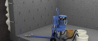
Definition: Bottom-soaked compression devices
Calculation procedure
1.Calculate the relative deformation value for each load;
2. Construct a graph of relative deformation versus load;
View of the graph of relative deformation versus load
3. Calculate relative subsidence and macroporosity.
Strength properties of soils.
Soil shear resistance
Shift
- this is the minimum shear stress that causes a permanent displacement at a fixed normal load.
The ratio of normal and shear stresses during shear is determined by Coulomb's law, which is expressed by the relationship: τ =σ tanφ+c.
τ-
value of tangential stresses in MPa,
σ —
the value of normal stresses in MPa,
φ –
angle of internal friction in degrees,
c –
adhesion in MPa.
Ground displacement diagram
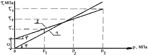
Soil shear resistance. 1- sandy soil, 2- clay soil.
Definition:
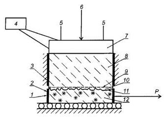
Schematic diagram of the installation for determining the shear resistance of thawing soil in contact with frozen soil GOST R 53582-2009 “Soils. Method for determining the shear resistance of thawing soils.” 1- dial indicator for measuring shear deformations; 2 — movable holder; 3 - fixed holder; 4 - device for creating and regulating the temperature of the thermal stamp; 5 — dial indicators for measuring settlement deformation; 6 - vertical load; 7 — thermal stamp; 8 - thawed soil; 9—cut plane; 10—near-contact layer (thawing soil); 11 - interface between thawing and frozen soil; 12—frozen soil; P is shear load.
Calculation procedure
1. Plot a graph of shear resistance versus normal load and straighten the resulting curve. To simplify the determination of indicators, the scales of the coordinate axes should be the same.
2. While maintaining an equal scale, remove from the graph the adhesion value, which is equal to the value corresponding to the intersection of the straight line with the ordinate axis (C)
and use a protractor to measure the angle of inclination of the straight line
(φ).
Types of subsidence soils
There are several types of soils prone to subsidence:
- clay;
- loams;
- loess;
- loess-like sandy loams;
- sands.
Ash deposits and industrial waste (for example, grate dust) have the same properties.
Separately, it should be noted bulk soils that are formed when leveling complex terrain or filling pits and ravines. They have a heterogeneous composition and compress unevenly under the influence of their own weight or loads. The total subsidence of various types of soil can vary from a few centimeters to 2 m.
Russian cities are suffering significantly from land subsidence. About 3.5 million sq. km of the country's territory, or 20% of its area, are soils prone to subsidence. More than 500 cities are located on them, and every sixth building is built on loess soil.
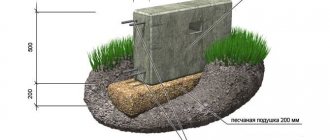
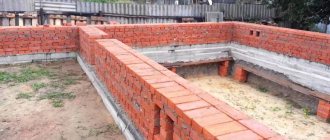
Choosing a foundation
The foundation of the house must ensure its long-term operation, the absence of distortions and subsidence. Embankments are classified as complex soils, so the choice of foundation should be taken seriously and wisely. The best option would be to contact specialists who can responsibly assess the construction conditions and, when they take on the work, guarantee a high-quality result.
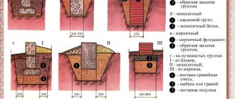
When laying a foundation on bulk soils, it should be taken into account that:
- a monolithic reinforced concrete slab located under the entire building area will distribute the loads as much as possible and protect the structure from uneven subsidence. The option is reliable, but expensive;
- a strip foundation will require an in-depth assessment of the condition of the soil and a more labor-intensive work process;
- piles can only be used if the embankment is sufficiently compacted and there are natural soil layers underneath it that have a high bearing capacity.
Most experts are inclined to believe that the optimal foundation option for bulk soils is a monolithic slab with reinforced reinforcement. It has many advantages, including the reliability of the design, its durability and easy installation. They more than cover the high cost of the materials used.
The planned arrangement of the embankment and its technically competent compaction greatly simplifies the construction of the foundation and allows for more accurate predictions of possible changes or movements of the soil.
Reasons for subsidence
Ground subsidence can occur for various reasons:
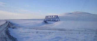
- Frozen soil is characterized by thermal subsidence that occurs when the temperature rises. Such processes occur in permafrost rocks.
- Loess and loess-like soils decrease in volume when soaked. The reason lies in the under-compacted state of the soil. It is a porous mass, the particles of which are held together by tiny salt crystals. The strength of their bond decreases sharply with increasing humidity, and the pores facilitate the easy distribution of water in the rock. The salt quickly dissolves and the soil structure collapses. As a result of this process, drawdowns are formed. Such soils are typical for steppe or semi-desert regions.
- Another reason is dynamic effects on the soil, which lead to vibrational subsidence.
Description
Foundation settlement is a very important characteristic; it changes over time and depending on the soil. There are reasons why uneven subsidence usually occurs:
- Saving on materials for the foundation and purchasing cheap and low-quality materials.
- Cheap and unskilled labor.
- Incorrect calculations were made of the depth of the foundation and the level of proximity to groundwater.
- No drainage system.
Purposes of determining draft:
- determine the amount of drawdown;
- perform accurate settlement calculations for foundations made of different materials;
- calculate possible deformations and physical changes.
Reasons for foundation settlement
The composition of the soil is one of the main reasons why the foundation of a house settles. The soil is divided into types and each has its own strength. The most durable types of soil cover are rocky soil and dispersed soil. In another way, these soils are called non-cohesive, since they will not retain moisture.
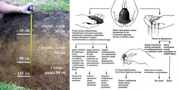
Determining soil type manually
The first type of soil is based on monoliths, and the second type consists of mineral grains of various sizes. But there are cohesive types of soil, they absorb and retain moisture, so the main component of these types of soil is clay, which is why the soil layer acquires the property of mobility and deformation. During the cold season, the moisture contained in these types of soil freezes and the soil layer expands. The first reason is the cohesive soil layer of the soil. The second reason is the design features of the base of the house. The third reason is the incorrectly distributed pressure of the walls on the foundation. When building a house, all these factors should be taken into account so as not to encounter this problem in the future.
Conclusion
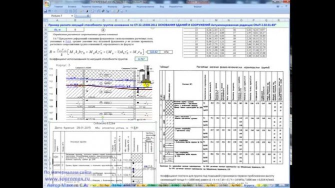
All calculation options are good in their individual cases. At the moment, all these design processes have been simplified due to the emergence of computer programs and professional software. But, as always, the most reliable knowledge is that obtained experimentally, and these parameters are taken as the standard and critical information.
When constructing a building, be sure to pay special attention to the foundation and such an important parameter as settlement, as it affects the strength and reliability of the structure.
Draft calculation
Calculation of settlement is a very important measure during the construction of a building. After all, the foundation is the foundation of the house, so the reliability and safety of operation depends on its integrity.
The subsidence of a new building on homogeneous soil can be 10-12 centimeters.
There are several basic accepted standards: if the soil is heterogeneous, then the settlement without consequences can be 5 centimeters, for multi-storey buildings - 2-3 cm.
Any subsidence in excess of this norm can be fraught with the appearance of cracks and destruction of supporting structures. This affects the safety of people in the building and the operation of the premises. If the house is multi-story and residential, then there is a risk of losing the health or lives of a large number of people.
It is almost impossible to make calculations on your own, but you can do this in a special simplified way. You can see an example of draft calculation in the video below.
Construction pit, strengthening pits
Foundations and basements are located below ground level. Therefore, the soil under the building must be selected and a construction pit must be formed. If accurate information about the structure and sequence of soil layers is required, then it is necessary to conduct soil studies, such as drilling wells, sounding or constructing pits. In accordance with the type of soil, a decision is made on the type and design of foundations. In addition, it is necessary to check whether water or gas supply pipelines, sewers, electrical or telephone cables pass under the site. After this, it is necessary to cut off the top layer of soil at the construction site. The uppermost layer of living soil is called the top (mother) layer of soil. It is especially rich in living organisms. This layer can be up to 40 cm thick. The top layer of soil should, if possible, be stored on the construction site, since it must later be used again for covering and landscaping the site. When excavating soil from a pit, care must be taken to ensure that its walls are strengthened either by slopes or by appropriate construction. Prolonged precipitation, aquifers, frost and dynamic shaking can contribute to the collapse of the pit walls. The bottom of the pit (bottom of the pit) must be horizontal, have the design profile and be smooth. Groundwater, water from soil layers, and surface water must be collected and drained. To have sufficient freedom of movement, it is necessary that there is a working space around the structure in the pit. This space should be at least 50 cm from the foundation formwork to the bottom of the slope of the pit wall.
Ensuring pit safety
Construction pits and trenches more than 1.25 m deep during excavation must be strengthened against collapse or subsequent sliding of the earth. On each side of the pit it is necessary to create protective strips at least 60 cm wide, which must be free, or care must be taken to ensure that the excavated soil or top soil cannot roll back into the pit. To assess the difficulty of loosening, loading, moving, laying and compacting, ordinary soils and rocky soils are divided into 6 classes. These soil classes provide information about the workability of construction soils. Based on this information, machines and mechanisms are selected and used for loosening, transporting and compacting earth and rocky soils. In addition, depending on the gradation of the construction soil on the ground or rocky soil, the angle of repose for construction pits is established. It is less than the angle of repose. With a pit depth of up to 1.75 m and stable soil, a slope should begin at an angle of 45° at a height of 1.25 m above the bottom of the pit. In soils whose cohesion may deteriorate due to drying, water penetration, frost, or the formation of slippery surfaces, it is necessary to construct more gentle slopes or slopes with indents (berms). Steps in the stepped walls of construction pits must be at least 1.50 m wide; in this case, the depth of the pit should not be more than 3.00 m. They should also have slopes. When the pit depth is over 5.00 m or when there are deviations from the slope angles, it is necessary to calculate their stability. If additional loads and dynamic impacts are expected or if it is necessary to take into account strong washout of the slope walls of the pit, then the surfaces of the slopes must be covered with film or strengthened by applying a thin layer of concrete (shotcrete). In pits with a depth of more than 1.25 m, it is necessary to have stepladders protruding at least 1.00 m above ground level. For deep pits, stepladders must be replaced with flights of stairs. Since the construction of slopes requires large areas on the site, the walls of the pit can also be strengthened with lining. This is also necessary for soils saturated with moisture or soils with uniform grain. The structure is a vertically standing wall made of beams or steel crossbars, which are lined along the entire plane with full-length beams at least 5 cm thick. This prevents the collapse of the pit wall. To prevent the collapse of the pit walls, the framing beams must extend at least 5 cm beyond the pit wall. The beams should support the ground of the wall with their entire plane. Construction with horizontal formwork (reinforcement with beams) must be installed continuously following the construction of the pit. This work should begin with a pit depth of 1.25 m. When constructing between frame or steel posts installed in boreholes, the beams are installed horizontally between the flanges of vertical steel posts. The beams must be so long that the depth of the supporting part corresponds to at least a quarter of the width of the flange. The beams must be secured with boards and wedges, and the wedges should, in turn, be secured with boards to prevent them from moving. When constructing vertical formwork in narrow pits, vertical beams with their lower ends are driven into the bottom of the pit and secured with horizontal wooden ties at a distance of 1.75 m from each other. Wooden ties must have a cross-section of at least 12 x 16 cm. The walls must be secured with construction as the pit is being excavated. The requirements for this type of construction correspond to the requirements for construction with horizontal formwork. If the pit is strengthened with sheet pile walls, then before the start of excavation work, sheet pile profiles are installed in the ground. Tongue profiles or sheet piling beams have so-called locks on their long sides, which serve as guides when driving in the tongue. Due to the fact that sheet piles can absorb large tensile and compressive loads, bracing and stiffening of sheet pile walls must be arranged at greater distances in the longitudinal direction than in other cases of construction. Sheet piling walls have the advantage that they are largely waterproof. Therefore, they are used to strengthen the walls of pits during hydraulic engineering work. Deep excavations near roads with heavy traffic and built-up areas are reinforced with walls made of bored piles. For this purpose, wells are drilled in the ground. Reinforcement is inserted into them. Then they are concreted. The piles may stand directly next to each other or at some distance. In this case, the gaps between them are filled with concrete walls.
Algorithm for performing the calculation. Version – SP 50-101-2004
When developing the program, clause 5.5.7 was used; 5.5.8; 5.5.10; 5.5.11; 5.5.25; 5.5.31; 5.5.32; 5.5.33; 5.5.35; 5.5.36; 5.5.37; 5.5.38; 5.5.39; 5.5.40; 5.5.41; 6.1.11; 6.1.13; 6.1.15; 6.1.17; 6.1.18.
In contrast to SNiP 2.02.01-83*, the design diagram of the foundation is in any case adopted in the form of a linearly deformable half-space. Therefore, for foundations with plan dimensions b>10.0 m, when determining pressures, the reduction in pressure by subtracting the household pressure is taken into account in the same way as for foundations with small base dimensions. It is accepted that the dimensions of the pit can be quite large.
According to clause 5.5.41, the lower limit of the compressible thickness of the foundation is taken to the level at which the domestic pressure is five times greater than the additional one for a foundation width less than or equal to 5 m (k = 0.2), twice for a width greater than 20 m ( k=0.5). In the range of foundation widths greater than 5 and up to 20 meters, the value of k is determined by interpolation.
In this case, the depth of the compressible thickness is taken to be no less than b/2 for b ≤ 10.0 m and (4+0.1b) for b>10.0 m.
According to clause 5.5.11, to determine the design resistance of the foundation, the values of φII, cII and γII are taken as the weighted average for the soil layer of thickness z below the base of the foundation: z= b/2 for b <10.0 m and z = 4+0.1b for b ≥10m.
The main difference between calculating settlement according to SP 22.13330 and DBN V.2.1-10-2009 from the methods described above is taking into account the influence of pore pressure.
Water retention
The construction of structures usually requires dry pits. The ingress of surface water (overwater), water flowing over the impermeable layer, or groundwater into the pit causes the risk of collapse of the slopes and walls of the pit. In order to eliminate this danger, it is necessary to prevent water from entering the pit or, accordingly, to remove water that has entered there. All measures to keep the pit dry are called water retention. When removing water from pits or trenches, a distinction is made between open water retention and water reduction. With open water retention, surface water or water in the soil layers entering the pit is collected in the deep part of the pit, in the so-called pump swamp, outside the perimeter of the building under construction and pumped out of the pit. Therefore, the bottom of the pit must be planned in such a way that slopes pass to this place. Drainage pipes or ditches can be installed along the edges of the pit, in which water from the soil layers or seeping water coming out of the slopes should be collected, which should then be diverted to the pump swamp. With the help of these measures, waterlogging of the pit bottom is prevented and normal work on foundation construction is ensured. Open retention of water is also possible when the bottom of the pit lies to a small extent below the groundwater level. If the base of the pit lies deeper than the existing groundwater level, then a lowering of the groundwater level is required. With the help of suction pipes, which are placed at short distances over the pit area and connected by a ring pipeline connected to a pump-out pump, the groundwater level is lowered and kept below the level of the bottom of the pit by at least 50 cm. In this way, the pit can be kept dry for carrying out foundation work. However, it is necessary to ensure that the water drawdown does not lead to sedimentation of the structure, does not affect the water supply and does not lead to environmental changes.
Ground pressure distribution
Due to the weight of the structure, compressive stresses arise in the foundations, which must be distributed over the foundation soil as evenly as possible. It is simply assumed that the pressure from the foundation to the ground extends at an angle of 45°. In reality, the pressure is distributed in a bulbous shape under the base of the structure. This produces lines of equal compressive stresses, called isobars. The distribution of these isobars is also called the “pressure onion”. The distribution of isobars shows that the compressive stresses under the sole are the highest. In the case of a point foundation, the stresses already at a depth equal to twice the width of the foundation base are almost zero. In the case of strip foundations, this occurs at a depth equal to three times the width of the base. Isobars of different foundations should not intersect, since stress increases in the area of intersection. This can lead to unpredictable settlements of the building (structure).