Foundations for equipment differ from the foundations of residential or industrial buildings not only in size. The essence of the differences lies in the very design of such foundations. After all, such foundations must withstand not only static (load-bearing) loads, but also dynamic loads, the source of which is the equipment fixed to the foundation.
In addition, the conditions in which the foundation for the equipment is operated are, to put it mildly, far from ideal. Indeed, in addition to the vibration of the body, such a foundation also absorbs a lot of aggressive substances - lubricants, oils, coolants and other substances that act on the body of the foundation in the most destructive way.
But in this article we will tell you not about the differences between a classic foundation and a foundation for equipment, but about a method of constructing structures that can withstand both the mass and vibration of any machines and mechanisms.
Requirements for foundation structures for equipment
The requirements for foundations for industrial equipment are high according to various criteria. This is due to the fact that they experience diverse loads and are often exposed to aggressive substances.
Foundation with pit
The foundation structure for the equipment must have the following properties:
- significant strength to withstand dynamic and static impacts from the installed mechanism;
- chemical resistance (inertness);
- significant mass providing resistance to vibration loads (vibration damping);
- minimal deviations from the planned dimensions, that is, the dimensions of the support must almost completely correspond to the design parameters;
- larger support area than the mounted unit.
High strength and resistance to chemically active components determine to a large extent the service life of the base and, in some cases, of working units.
Aggressive substances that destroy the support are:
- lubricants;
- coolants;
- various technical oils;
- various fuels and others.
The damping of vibrations by a massive base from the operation of mechanisms with dynamic loads (an example of such units are rolling stands, hammers) is of great importance. This is due to the fact that vibrations cause a reduction in the service life of the entire building and the equipment itself, as well as neighboring mechanisms.
Vibrations occur due to the presence of unevenly rotating parts in the machine: cutting tools, rotors, pulleys and others.
In addition to the dimensions (length, width, height) of the supporting structure, the locations of the fastening elements must also coincide with the drawing. Only minimal differences are acceptable.
If not provided for by the design features of the equipment, then there should be no slopes on the installation site so that installation work can be completed correctly and quickly.
Units of small mass (up to 2 tons), which do not cause significant dynamic effects on the support, are mounted directly on reinforced concrete floors or interfloor ceilings. If required, they are prepared accordingly, strengthening the base by reinforcing and pouring concrete. Such supporting structures are classified as foundations of the first group.
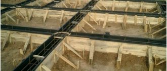
Prepared base
General regulations
The constructed foundation for the installation of equipment must ensure the safety of the labor process (correspond to the current loads in terms of strength) and ease of maintenance of the mechanisms mounted on it. For this purpose, pits (or basements) are made and other utilities are laid.
In addition to the considered criteria that support structures for equipment must meet, the following requirements are imposed on foundations with dynamic loads and the process of their construction:
- it is necessary that the construction and design of foundations be carried out by competent specialists with a high qualification level, as well as experience in carrying out such work;
- to create a project, it is necessary that the initial data be available in the required volume and be interpreted only by professionals;
- the construction process must be accompanied by constant quality control of the work;
- it is necessary that the actions of all participants in the construction process are clearly coordinated;
- the constructed foundations must be used for the intended purpose specified in the design documentation;
- for construction, materials that meet regulatory requirements should be used;
- maintenance of the foundations should be carried out so that the structure lasts for the longest possible period;
- reliability and the greatest possible ease of fastening (as an example - anchor bolts embedded in concrete).
The video further provides recommendations for arranging foundations for machine tools.
All work on the design and construction of support structures for mechanisms must be carried out by specialists to achieve compliance of the constructed structure with technical specifications and current standards. An important factor is also the efficiency of the foundation structure being erected, due to which all costs are reduced to a minimum.
Variety of equipment
When it comes to bases for equipment, it should be borne in mind that there is a wide variety of equipment, grouped into separate groups. Regulatory documents require that the foundation for each of them be calculated taking into account the operational features of the mechanisms.
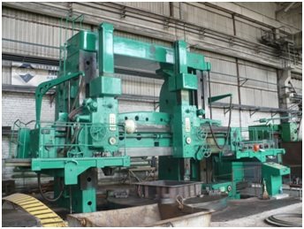
Metalworking machine
Foundation structures are designed and erected for the following groups of machines:
- with crank mechanisms: piston compressors, sawmill frames, diesel engines, motor-compressors;
- turbo units: turbo blowers, turbo compressors, turbo generators;
- electrical machines such as synchronous compensators and motor generators;
- stamping or forging hammers;
- rental equipment (auxiliary or main type);
- piledrivers designed to break scrap;
- rotary kilns;
- crushers (gyration, tube, jaw, roller) and milling units;
- metal cutting machines;
- press;
- molding machines (used both in foundries and in the production of reinforced concrete blocks).
Each group of equipment with dynamic loads has its own characteristics of foundation calculations. This is due to the peculiarities of the forces that arise during the operation of machines.
Monolithic base of complex design
Types of bases
To install the units, different foundation structures are used that meet the requirements set by the standards.
In practice, machines are installed mainly on the types of support structures presented in the table below.
| № | Type of foundation structure | Characteristics of the constructed base |
| 1 | slab foundation without basement | it is poured only on the ground floor, it is expensive due to the significant consumption of building materials and high labor costs, but its massiveness well dampens the resulting vibrations |
| 2 | frame base equipped with a grillage of beams | is capable of withstanding high-frequency vibrations without negative consequences, therefore it is often used for the installation of impact mechanisms |
| 3 | wall support structure (is a modification of strip-type bases) | it is erected from the second floor, the effective load from the units with this support structure is taken by the external (load-bearing) walls, as well as internal partitions |
| 4 | base-floor with a basement | is located above the first floor, transmits vibrations (arising during the operation of machines) to the interfloor floors (building frame), and is capable of withstanding only static loads or vibrations with insignificant amplitude |
The most modern option for light or medium-heavy mechanisms is to install bases with springs or other types of vibration supports that dampen vibrations that occur during operation of the units.
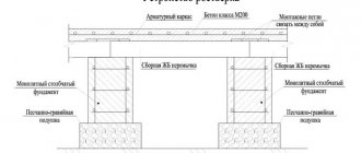
Dampers (vibration dampers) can be especially easily installed under frame-type bases. At its core, a floor foundation equipped with a basement is the same slab, only built from ready-made reinforced concrete blocks laid on floor beams.
The given foundation structures are divided into 2 types:
- basementless (it almost completely lacks a part located above the floor);
- basement (with a well-developed above-ground section).
The latter option can have a wall or frame form. It is characterized by a large height above the floor plane.
Foundations by design can also be prefabricated, monolithic, prefabricated-monolithic. They come in the following forms:
- rectangular;
- tape;
- stepped;
- shaped;
- trapezoidal.
It is possible to use piles of different types as foundations for units with periodic loads. A slab or strip grillage is installed on top of the supports. Impact-type mechanisms must be mounted on solid reinforced concrete piles.
The distances between installed pillars are regulated by SP 24.13330. It should not exceed 10 of their diameters. The vibrations of pile foundations can be calculated using the relevant subsections of this document.
Various blocks and slabs (hollow or solid) are used as elements of prefabricated structures.
The most massive units, characterized by great weight, are mounted only on a slab-type foundation. The slabs are equipped with recesses, holes and cutouts used for the installation of machines and their maintenance during operation.
Individual and group foundations
The equipment is mounted on individual or group foundation structures.
Group basis
Group foundations are designed for installation of several mechanisms of light or medium weight (up to 8 tons) with a rigid frame and normal operating accuracy, operated with a predominance of static forces. Their thickness is usually 150-250 mm. They often serve only as bases. The single support is mainly concrete (or reinforced concrete) floors. But in practice there are other design options.
Mechanism frames are considered rigid when the ratio of their length to height is no more than 2 to 1.
Individual type foundations are built for precision equipment with medium or heavy weight, which operates with dynamic loads of moderate or significant magnitude. Such supports, in addition to removing vibrations from machines and ensuring their correct working position, also isolate the units from each other. This prevents the transfer of vibrations between them.
Lightweight machines, or medium-weight units with a predominant static type of load, are often mounted directly on the floor or interfloor ceiling (the so-called foundation of the first type). If necessary, such a base is reinforced with a concrete screed (while laying reinforcement), also increasing its thickness.
Under large units, foundations shrink. This process can continue for a long time. Therefore, the installation level (horizontal and vertical) of the machines should be checked.
Materials used for the construction of foundations
Materials for the construction of foundations for machines of various sizes and weights must be durable and resistant to various aggressive environments. Therefore they use:
- ready-made reinforced concrete blocks (they are tied together during construction);
- reinforced concrete obtained by pouring a reinforcement cage located inside the formwork;
- metal (for creating pile structures with a grillage in the form of a frame);
- reinforced concrete with metal (a metal grillage is installed on concrete blocks or piles).
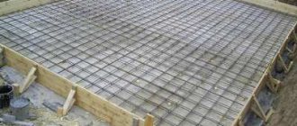
Scheme of a reinforced concrete monolithic slab
Baseless and basement foundations are erected using concrete grades M200-M300 (for light units) or M400 (for heavy machines), class B15
In private workshops or home workshops, rubble stone is also used for the construction of foundations (the result is rubble concrete).
The use of certain materials for specific mechanisms is regulated by building codes.
The construction of foundations made of bricks laid on cement mortar is also common, but rare. In this case, the groundwater must be located deep (below the base of the base). Basically, such supports are made for light vehicles (weighing no more than 4 tons), and their thickness is no less than 50 cm. Sand-lime brick cannot be used in this case.
Previously, lightweight units were installed on wooden floors, but now this is rarely seen. This is due to the fact that the tree quickly warps and changes its shape. Such foundations can only be used as temporary supports.
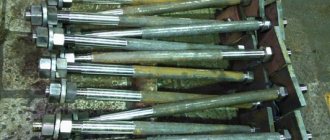
The mounted equipment is connected to the base using bolts. Their parameters are established by the requirements regulated by SP 43.13330. If the mechanism creates a shock load or strong vibrations during its operation, requiring the use of bolts with a diameter of more than 42 mm, then their removable types are used.
The gap from the lower end of the fastener to the foundation base should be more than 10 cm.
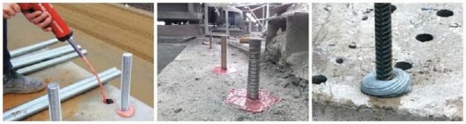
Recently, the use of chemical anchors to secure units has become increasingly popular.
The best option for supporting mechanisms with dynamic loads is monolithic reinforced concrete. When using metal structures or ready-made (factory) blocks, they must meet all the requirements for foundations for equipment.
Chemical anchor
So-called chemical anchors have recently become widespread. In the finished foundation of sufficient depth, wells are drilled at the locations where the machine is mounted. Anchor bolts are inserted into these wells and filled with a special adhesive composition. After polymerization of the glue, a strong bond between the anchor and concrete is ensured.
Design of foundation structures
Designing foundations for equipment is the initial stage of their construction, which is carried out according to technical specifications. All calculations are carried out in accordance with current building codes and regulations.
Foundation for a group of mechanisms
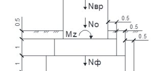
The initial data for carrying out the necessary calculations to determine the operational parameters of the supporting structure are:
- soil characteristics (freezing depth, structure, location of groundwater, bearing capacity and other parameters);
- effective static load;
- calculated dynamic forces (vibration magnitude);
- supporting area of the unit frame;
- temperature regime of operation of the erected base;
- operating conditions of the installed mechanisms, as well as their operating mode;
- the nature of the development surrounding the machine (shows the effect of external forces on the support being created).
The project must also take into account the presence of aggressive environments and measures to protect the base from them.
The hydrogeological properties of the soil are determined through preliminary appropriate engineering studies. On loose soil types, the construction of more massive supports is required than on rocky rocks.
Static load is the weight of the mechanism, which is indicated in its passport or operating instructions. Based on the calculated pressure on the grillage, the magnitude of the dynamic forces is determined. They occur during operation of units due to the movement of their components.
The found pressure value is adjusted taking into account 2 coefficients: constant soil settlement (it is 0.7÷1.0) and working conditions (starting from 0.5, in relation to a forging hammer, to 1.0 when installing screw-cutting turning units ).
The value of the first constant depends on the degree of soil moisture.
When performing calculations, it is necessary to take into account that the total effective (static and dynamic) load transmitted to the base base must be less than the bearing capacity of the soil.
The foundations on which it is planned to mount the mechanisms with further filling with concrete mortar (which must be indicated in the design documentation) are handed over for installation with a height of 50-60 mm below its design value. If concreting is not provided, all base parameters must correspond to the working design.
The design decisions taken must ensure the durability, reliability, and cost-effectiveness of the foundation being created. In practice, several projects are often created, and then compared from a technical and economic point of view. In this case, the optimal option is selected.
The reliability of the structure being created must be ensured at all stages of its construction.
Recommendations for calculating foundations for equipment installation are given in the video below.
In general, knowing the mass of the mechanism, the type of soil underneath it, as well as its operating conditions, you can calculate the required parameters of the supporting structure. The foundation being constructed must comply with the technical conditions for its construction. Also, the design takes into account sanitary, epidemiological and environmental standards.
Vertical milling machine on a metal frame
Bases for metalworking machines
Metal-cutting machines come in a large number of varieties. They are used to perform a variety of operations. Usually their weight does not exceed 25 tons. Only unique cars have more weight.
You can calculate the dimensions of the bases using special tables. They speed up and simplify calculations. An example of such a table is presented below. It provides formulas for calculating the height of the foundation structure for different groups of metal-cutting machines depending on the length (L) of the base, expressed in meters.
| № | Machine names | Base height, m |
| 1 | Semi-automatic and automatic turning | 0.2*√ L |
| 2 | Lathe horizontal broaching | 0.2*√ L |
| 3 | Rotary milling and conventional milling horizontal and vertical | 0.6*√ L |
| 4 | Carousel (automatic and semi-automatic vertical) | 0.6*√ L |
In a simplified case, the base area for metal-cutting machines is determined by a similar parameter of the bed of the installed mechanism.
The height of concrete structures is calculated according to the table above. In this case, for precision machines, an amendment is made in the form of a coefficient of 1.2. The calculated table value of the base thickness is multiplied by it. It must be taken into account that the distance from the mounting anchors to the edges of the base should be left more than 12 cm, and from the frame of the mechanism - at least 10 cm.
If light machines are installed (weighing a maximum of 4 tons), for example, drilling, gear cutting, milling, then it is enough to build a base 25 cm high for them. In this case, reinforcement can be omitted.
When the weight of the mounted equipment is more than 12 tons or the machines create strong dynamic loads during their operation (for example, cross-planing, slotting), then reinforcement is laid. This is done before pouring concrete. Steel reinforcement bars (with a cross section of 6-8 mm) are very often used in work. They make a mesh with cells approximately 15 by 15 cm. In this case, the distance from the frame to the reinforcement should be about 5 cm.
Why vibration support is a bad option
The foundation of the machines is, as a rule, 1-2 or more meters of concrete, in which anchor bolts are fixed. The machine is leveled and then firmly screwed to the foundation. In this case, the tightening torque of each support affects the overall geometry of the machine. Therefore, the installation of a machine requires a very highly qualified specialist - a commissioning operator who understands how the machine behaves when tightening or loosening a particular attachment point. When installed correctly, the machine has an ideal geometry, and the rigidity of the foundation increases the rigidity of the machine. As a result, processing accuracy is increased and wear on the machine guides is minimized. If vibration supports are used, the machine bed “walks” under load, which negatively affects both the quality of the manufactured part and the service life of the machine itself.
Regulatory framework for the construction of foundations for cars
The design of foundations is regulated by a number of construction standards, GOSTs, and rules. Compliance with the requirements presented in them leads to obtaining a high-quality result.
Exposed formwork with reinforcement cage
The main document for designing foundations for machines with dynamic loads is SP 26.13330.2012 (this is the new edition of SNiP 2.02.05-87). This set of rules is based on a number of other regulatory documents.
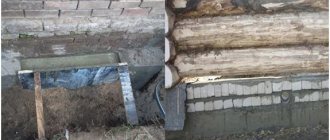
Description of this defect
Often, without a design solution, heavy equipment and various frames for its fastening are installed directly on the roofing carpet itself. Soft rolled roofing is not initially designed for such loads, and over a period of time, heavy equipment gradually pushes through the rolled roofing, compromising the integrity and tightness of the roofing carpet. The situation is aggravated by the presence of alternating dynamic loads from equipment, vibrations that occur during its operation and the effects of wind loads, leading to accelerated destruction of the roof.