Load calculation
The load on the pillars is calculated taking into account all static and dynamic influences. Constant impacts include the total weight:
- supports;
- fittings;
- consoles;
- flange bases;
- lamps;
- wires
Calculations are performed using coefficients developed for various configurations of racks, consoles and luminaires.
The increase in loads caused by gusts of wind is also taken into account in accordance with SNiP 2.01.07-85. The data is taken from a lookup table for windy areas.
Drawing up a design diagram of a beam
In order to draw up a calculation scheme, you do not need much knowledge. To do this, it is enough to know the size and shape of the cross-section of the element, the span between the supports and the method of support. The span is the distance between two supports. For example, you use beams as supporting floor beams for the load-bearing walls of a house, between which there are 4 m, then the span will be equal to 4 m.
When calculating the deflection of a wooden beam, they are considered to be simply supported structural elements. In the case of a floor beam, a diagram with a load that is evenly distributed is adopted for the calculation. It is denoted by the symbol q. If the load is concentrated in nature, then a diagram with a concentrated load, denoted F, is taken. The magnitude of this load is equal to the weight that will exert pressure on the structure.
Calculation of the height of lighting supports
The standard height of lighting poles varies from 4 to 12 meters. Its calculation is carried out in accordance with the “Rules for Electrical Installations”.
- The installation height of lamps above the roadway must be at least 6.5 m . In this case, structures with cantilever extensions installed on power supports are used. When servicing lanterns from an equipped telescopic tower, it is allowed to place the luminaires above or below the high-voltage line with a horizontal distance of at least 0.6 m. If other maintenance methods are used, the lanterns are mounted below the overhead line with a vertical distance of 0.2 m and a horizontal distance of 0.4 m. The overhead height of the support will be 8-9 meters.
- The installation height of lamps above pedestrian areas should be from 3 m . In park areas, floor lamp-type structures are often used. They have an attractive design and gently diffuse light in all directions.
- Minimum height of decorative lighting supports for buildings, lawns, etc. not regulated by standards.
- Installation of lanterns below ground level is permitted when organizing a drainage or other drainage system.
Important! Metal support structures are most resistant to temperature changes. They can be used in all climate zones.

Coefficients φ of longitudinal bending of centrally compressed steel elements
| Element flexibility | Values of φ at Ry, MPa | |||||
| 200 | 240 | 280 | 320 | 360 | 400 | |
| 10 | 0,988 | 0,987 | 0,985 | 0,984 | 0,983 | 0,982 |
| 20 | 0,967 | 0,962 | 0,959 | 0,955 | 0,952 | 0,949 |
| 30 | 0,939 | 0,931 | 0,924 | 0,917 | 0,911 | 0,905 |
| 40 | 0.906 | 0,894 | 0,883 | 0,873 | 0,863 | 0,854 |
| 50 | 0,869 | 0,852 | 0,836 | 0,822 | 0,809 | 0,796 |
| 60 | 0,827 | 0,805 | 0,785 | 0,766 | 0,749 | 0,721 |
| 70 | 0,782 | 0,754 | 0,724 | 0,687 | 0,654 | 0,623 |
| 80 | 0,734 | 0,686 | 0,641 | 0,602 | 0,566 | 0,532 |
| 90 | 0,665 | 0,612 | 0,565 | 0,522 | 0,483 | 0,447 |
| 100 | 0,599 | 0,542 | 0,493 | 0,448 | 0,408 | 0,369 |
| 110 | 0,537 | 0,478 | 0,427 | 0,381 | 0,338 | 0,306 |
| 120 | 0,479 | 0,419 | 0,366 | 0,321 | 0,287 | 0,260 |
| 130 | 0,425 | 0,364 | 0,313 | 0,276 | 0,247 | 0,223 |
| 140 | 0,376 | 0,315 | 0,272 | 0,240 | 0,215 | 0,195 |
| 150 | 0,328 | 0,276 | 0,239 | 0,211 | 0,189 | 0,171 |
| 160 | 0,290 | 0,244 | 0,212 | 0,187 | 0,167 | 0,152 |
| 170 | 0,259 | 0,218 | 0,189 | 0,167 | 0,150 | 0,136 |
| 180 | 0,233 | 0,196 | 0,170 | 0,150 | 0,135 | 0,123 |
| 190 | 0,210 | 0,177 | 0,154 | 0,136 | 0,122 | 0,111 |
| 200 | 0,191 | 0,161 | 0,140 | 0,124 | 0,111 | 0,101 |
| 210 | 0,174 | 0,147 | 0,128 | 0,113 | 0,102 | 0,093 |
| 220 | 0,160 | 0,135 | 0,118 | 0,104 | 0,094 | 0,086 |
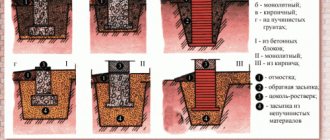
Calculation of lighting support for stability
A concrete foundation is placed under the support. The size of the base is calculated taking into account the bearing capacity of the soil. If such data is not available, then a design unit of compressive strength equal to 150 N/m2 is adopted, corresponding to the soil of maximum density.
The depth of the foundation is determined depending on the height of the pillar. The base has a square cross-section to ensure even distribution of loads in all directions.
The stand is concreted with a certain depth, or it is fixed to the foundation using embedded elements. It is important to install the pole strictly vertically. Maximum deviations from the vertical are regulated by standards.
Calculation of lighting support for stability is carried out with experimental tests. In this case, a test is performed for bending, torsion, and capsizing under the influence of dynamic forces.
Modifications of supports are created for use in various conditions. It is important that their technical parameters comply with the recommendations of building regulations, geological and climatic features of the area.
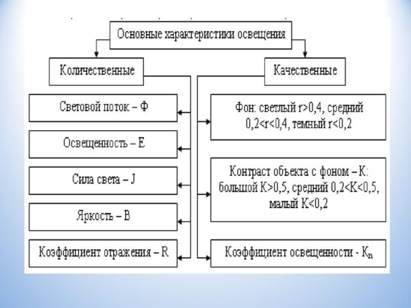
Lighting characteristics
To begin with, the light that the human eye perceives is at a wavelength of 380-780 nm. There are eight basic lighting characteristics that help describe lighting:
- Luminous flux is optical radiation, which we call light. It is measured in lumens and in the formulas below will be denoted by the Latin letter F. The higher the luminous flux value, the brighter the illumination will be (provided that other characteristics are equal).
- Luminous intensity represents the density of luminous flux in current space relative to the solid angle axis. Symbolized by the letter I, measured in candelas.
- Solid angle - W. We are talking about a certain space located inside a conical surface. The unit of measurement is steradians.
- Illumination is a numerical value of light flux density. It is measured in lux and is designated by the letter E.
- Brightness is the surface density of light intensity. The ratio of candelas per square meter is used for measurement and L is used for designation.
- Glare - P, which determines the ability of the device to create a blinding effect.
- Pulsation coefficient - measured as a percentage, used to assess the depth of vibration of a lighting device. Denoted by the letter K.
- Discomfort criterion - M. Allows you to evaluate uncomfortable glare, potentially causing pain in the eyes in the case of uneven distribution of flashlights in a person’s field of vision.
Initial parameters method
The initial parameters method is a fairly universal and simple method. Using this method, you can write a formula for calculating the deflection and angle of rotation of any section of a beam of constant stiffness (with the same cross-section along the length.)
The initial parameters are understood as already known movements:
- deflections in supports are zero;
- in a rigid embedment, the deflection and rotation angle of the section are zero.
Taking into account these tricks, they are also called boundary conditions, and displacements in other parts of the beam are determined.
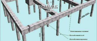
Calculation of an eccentrically compressed column.
Here, of course, the question arises: how to calculate the remaining columns, since the load will most likely be applied to them not in the center of the section? The answer to this question greatly depends on the method of attaching the canopy to the columns. If the canopy beams are rigidly attached to the columns, then a rather complex statically indeterminate frame will be formed, and then the columns should be considered as part of this frame and the cross-section of the columns should be calculated additionally for the action of the transverse bending moment. We will further consider the situation when the columns shown in the figure 1, are hingedly connected to the canopy (we are no longer considering the column marked in red). For example, the head of the columns has a support platform - a metal plate with holes for bolting the canopy beams. For various reasons, the load on such columns can be transmitted with a fairly large eccentricity:
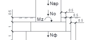
Figure 2 . The eccentricity of the application of a concentrated load to a column due to deflection of the canopy beam.
The beam shown in Figure 2, in beige color, will bend slightly under the influence of the load (why this will happen is discussed separately) and this will lead to the fact that the load on the column will not be transmitted along the center of gravity of the column section, but with an eccentricity e and when calculating the extreme columns, this eccentricity must be taken into account. A more accurate determination of eccentricities depends on the stiffness of the column and beam, but in this case we will not take into account the stiffness and, for reliability, we will accept the most unfavorable eccentricity value. There are a great many cases of eccentric loading of columns and possible cross sections of columns, described by the corresponding formulas for calculation. In our case, to check the cross-section of an eccentrically compressed column, we will use one of the simplest:
(N/φF) + (Mz/Wz) ≤ Ry (3.1)
Those. it is assumed that there is eccentric loading about only one axis.
In this case, when we have already determined the cross-section of the most loaded column, it is enough for us to check whether such a cross-section is suitable for the remaining columns for the reason that we do not have the task of building a steel plant, but we are simply calculating the columns for the canopy, which will all have the same cross-section for reasons of unification.
We already know what N , φ and R
Formula (3.1) after the simplest transformations will take the following form:
F = (N/Ry)(1/φ + ez·F/Wz) (3.2)
since the maximum possible value of the bending moment Mz = N·ez , why the value of the moment is exactly what it is and what the moment of resistance W is is explained in sufficient detail in a separate article.
The concentrated load N on the columns, indicated in blue and green in Figure 1, will be 1500 kg. We check the required cross-section under such a load and the previously determined φ = 0.425
F = (1500/2050)(1/0.425 + 2.5 3.74/5.66) = 0.7317 (2.353 + 1.652) = 2.93 cm2
In addition, formula (3.2) allows you to determine the maximum eccentricity that the already calculated column will withstand; in this case, the maximum eccentricity will be 4.17 cm.
The required cross-section of 2.93 cm2 is less than the accepted 3.74 cm2, and therefore a square profile pipe with cross-sectional dimensions of 50x50 mm and a wall thickness of 2 mm can also be used for the outer columns.
Note : In general, the bending moment from eccentricity in the most dangerous section, located approximately in the middle of the column height, will be 2 times less, and accordingly the required cross-sectional area will also be slightly smaller. But as I already said, when performing calculations by a non-specialist, an additional margin of safety will never hurt. Moreover, in this case we still accept a large cross-sectional area for structural and aesthetic reasons.
Calculations and standard solutions
To avoid labor-intensive calculations, which may result in errors without knowledge of physics and the use of a calculator, we recommend using standard solutions with minimal load on the column. Reliable movable hinge joints for mounting at an angle and distributing angular momentum will also help you get what you want. In this case, it is important to calculate how long such a support will withstand.
This approach allows you to calculate various furniture with steel supports, fastenings in the closet, while being confident in their reliability and durability. Adjustment usually allows the structure to be securely strengthened. Choose high-quality steel from a reputable Russian manufacturer, this way you can avoid purchasing low-quality products.
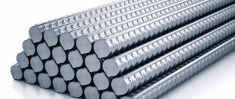
I-beam
Please note that I-beams are used somewhat less frequently due to their shape. However, we should also not forget that such a structural element can withstand much greater loads than an angle or channel, an alternative to which can be an I-beam.
It is worth calculating the deflection of an I-beam if you are going to use it as a powerful structural element.
We also draw your attention to the fact that it is not possible to calculate deflection for all types of I-beams. In what cases is it allowed to calculate the deflection of an I-beam? There are 6 such cases in total, which correspond to six types of I-beams. These types are as follows:
- Single-span beam with a uniformly distributed load.
- A cantilever with a rigid seal at one end and a uniformly distributed load.
- A beam of one span with a cantilever on one side, to which a uniformly distributed load is applied.
- Single-span beam with a hinged type of support with concentrated force.
- Single-span simply supported beam with two concentrated forces.
- Cantilever with rigid termination and concentrated force.
Metal beams
The calculation of the maximum deflection is the same, whether it is a steel beam or an element made of another material. The main thing is to remember those quantities that are specific and constant, such as the elastic modulus of a material. When working with metal beams, it is important to remember that they can be made of steel or I-beams.
The deflection of a metal beam made of steel is calculated taking into account that the constant E in this case is 2·105 MPa. All other elements, such as the moment of inertia, are calculated using the algorithms described above.
Moment of inertia
The geometric characteristic, which is called the moment of inertia, is important when calculating the deflection of a beam. The formula allows you to calculate this value; we will give it a little below.
When calculating the moment of inertia, you need to pay attention to the fact that the size of this characteristic depends on the orientation of the element in space. In this case, an inversely proportional relationship is observed between the moment of inertia and the amount of deflection. The smaller the moment of inertia value, the greater the deflection value and vice versa. This dependence is quite easy to track in practice. Every person knows that a board laid on its edge bends much less than a similar board in a normal position.
The moment of inertia for a beam with a rectangular cross-section is calculated using the formula: