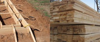
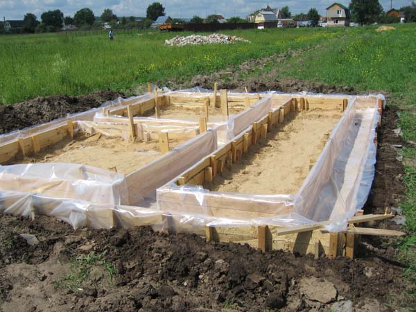
Wooden formwork for a strip foundation
The main task of the formwork is to hold the liquid concrete mass in the desired shape until the monolith completely hardens. Calculation of formwork is an integral part of the economic analysis of the costs of building a facility. How accurate the enclosing structures will be depends on their reliability. At the same time, correctly selected dimensions of formwork elements will prevent the occurrence of emergency situations. Every developer is interested in how to calculate the formwork for floors, walls, vertical supports and strip foundations. There are many different designs for pouring concrete.
Calculation of wooden formwork for a strip foundation
To calculate the formwork, we find out the geometric parameters of the monolithic tape:
- The length of the foundation base - we measure the perimeter and add to it the length of all load-bearing walls, if they are provided.
- Thickness of the strip base.
- Height. This part of the calculation can be difficult, since often the formwork is erected only on the surface of the soil, and the buried part is poured directly into the trench. But it is worth considering that such construction of foundations is applicable only for shallow structures. If the foundation is deep, then the formwork for it is made to the entire height of the tape, since such a structure requires a special approach - good insulation and high-quality waterproofing.
- Board sections. It comes in three sizes - 100, 125, 150 mm. The cost of the material depends on the choice of lumber thickness.
Important! Take into account and comply with the norms for the construction of formwork. If the width of the base is large, then boards made of 100 mm boards will not be enough when pouring concrete. Under the weight of the foundation, a board of small cross-section will move.
You need to approach the choice of material rationally. Before pouring concrete, we perform insulation. This will help keep the board suitable for further use.
Explanations for calculations
The calculation itself is quite simple and does not require a large amount of data on the shape and dimensions, which were obviously calculated before the start of construction.
The main data are:
- Length of the tape (includes the sum of the lengths of all elements of the building, taking into account the internal lintels for future walls.)
- The actual thickness of the proposed supporting structure.
- The height of the formwork panels for the foundation (only the height of the panel is required and, if in the lower part of the base the role of the formwork is played by soil, we do not take this height for calculation).
This approach will be an ideal solution for casting a strip foundation with shallow depth, which will lead to material savings.
Related article:
DIY strip foundation: step-by-step instructions. In the article we will look at the pros and cons of this foundation, the nuances of its correct pouring, as well as which brand of concrete is best to choose in order to get a high-quality structure.
An example of calculating formwork for a foundation
Calculation of formwork begins with input of initial data, here is an example:
- monolithic tape along the perimeter 12 by 11 meters according to plan - (12*2) + (11*2) = 46 meters;
- the length of the formwork structure is 46 * 2 = 92 meters (multiplied by 2 because there will be panels on both sides);
- base width – 0.5 meters;
- foundation height is 1.5 meters.
The input data is ready, we make calculations using the formulas:
- the total area of this structure is 92 * 1.5 = 138 m2
- when introductory to the width and height of a monolithic strip, use an edged board with a thickness of 25 mm;
- Now let’s calculate how much lumber will be needed for the panels - 138 * 0.025 = 3.45 m2;
- Using average indicators, we calculate how many bars with a cross section of 0.5 * 0.5 cm are needed. Often this indicator is calculated from the cubic capacity of the boards and is 30% of it - 3.45 * 0.3 = 1,035 m3
- We purchase materials 10% more, since unforeseen expenses arise - 3.45 * 0.1 = 0.345 m3.
To summarize, when building a strip foundation, based on the input you will need:
- edged boards 150*25 mm – 4 m3;
- block 0.5*0.5 – 1.5 m3;
- knitting wire with a cross-section of 0.8 cm – 12 m;
- spacer pins 40 cm in length, which are used for every 2 m, 1 pc. – 46 : 2 = 23 pcs.
At this stage, the calculation is considered complete. When calculating enclosing structures, use an online calculator - it is much simpler and more convenient.
Instructions for the calculator
Initial data
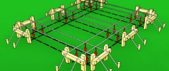
Total length (L) is the sum of all the lengths of the foundation surface. For example, for a picture L=2*L1+2*L2+2*L3+2*L4+2*L5+2*L6+4*L7.
The number of external corners is the corners where two supports will be installed (see picture).
Height (H) - the height of the formwork.
Step (F) - step of supports and racks.
Step (K) - step of intermediate ties between supports.
Formwork:
Length (A1) - the length of the board or plywood.
Width B1 - the thickness of the formwork (boards or plywood).
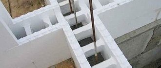
Height (C1) - the height of one board or plywood. For example, if the height of the foundation is 300 mm and the height of the board is 100 mm, then three boards are laid along the height of the formwork (as in the figure). In the same case, when plywood with a height of 300 mm is used for formwork, then C1 = 300mm.
Pegs, support 1, support 2, cross tie, stand, upper supports, support pegs:
A1 - C6 - dimensions of lumber that ensure the strength and stability of the structure.
Stock - here it is advisable to indicate 5 - 10% in order to avoid a shortage of lumber.
Design Features
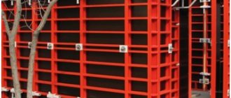
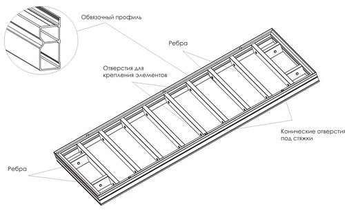
To create formwork supports with telescopic posts, a tubular steel metal structure is used, consisting of several elements:
- Lower guide support with a platform welded at the base and a threaded tensioner in the upper part of the pipe;
- Upper support with mounting holes for brackets and an upper welded flange that follows the dimensions of the platform in the base;
- A support nut that can move along the tensioner and serves as an additional lock for the strut in a given position;
- Support fork (unifork) – a metal platform with welded support rods for laying and holding I-beams;
- A tripod that provides additional stability to the support using bevels.
All elements of the racks are attached to two main parts, connected in a pipe-to-pipe manner. The lower pipe has a larger diameter and wall thickness, the upper one can be removed and fixed to the required height.
What requirements must the floor formwork meet:
— High strength and rigidity. Telescopic supports or volumetric racks must easily withstand not only the weight of the system as a whole, but also the enormous pressure exerted by the concrete. To achieve the desired result, it is extremely important to correctly select the components, perform error-free installation and provide a certain safety margin.
— Resistance to deformation. Formwork panels must be of sufficient rigidity so as not to deform under the pressure of concrete. Otherwise, height differences may occur in the future ceiling.
- Moderate weight. The lower the weight of the formwork system, the easier, faster and cheaper it is to install. You should always try to make the formwork as light as possible, but its reliability should not be compromised.
— Possibility of repeated use. Turnover is one of the most important technical characteristics of any formwork system. The use of high-quality components and regular maintenance allows you to use the same formwork up to 200 times. It should be remembered that the cost of systems for casting floors is always quite high.
- Safety. All ladders and railings in high-risk areas must be securely secured. Builder safety always comes first!
Types of formwork and materials used
When arranging the foundations for buildings and structures, various types of formwork are used.
These designs are divided into the following categories:
- vertical and horizontal;
- block and panel;
- adjustable, sliding and drive-up;
- removable and stationary.
Formworks are also differentiated according to the materials used. Today, the construction industry uses structures made of metal, wood and plastic. Combination devices are used quite often. As a rule, this happens when installing curved structures.
According to the options for influencing the poured solution, devices are divided into:
- ordinary;
- warming;
- with insulating gasket;
- special.
Based on the frequency of use for their intended purpose, formworks are divided into disposable formworks (disposed of after removal) and inventory formworks, which, after dismantling, are cleaned and put into storage until the next time they are needed.
Any type of formwork consists of the following parts:
- Shields. These products come in different sizes and configurations. Designed to fix concrete in a given shape.
- Supporting and load-bearing elements. These include stops, ties, jumpers and contractions. Necessary in order to fix the boards in the position provided for by the construction project.
- Fastening elements. Serve to give the structure strength, stability and reliability. Nails, screws, ties, bolts, angles and clamps are used.
When making calculations, it is necessary to take into account that the height of the formwork should exceed the concrete pouring level by 5-20 cm, depending on the type of foundation.
In private construction, structures made from boards are always popular, which, after dismantling, are sawn and used for firewood. Depending on the required smoothness of the surface that the hardened concrete will have, a slab or floorboard with selected edges is used in the manufacture of formwork. The second option is more expensive, but allows you to achieve a perfectly flat surface. Its finishing will take much less money than a wall with an abundance of bulges and protrusions. In addition to boards, you need to stock up on a sufficient supply of timber and substandard trimmings. This type of wood is necessary to create the form into which the concrete solution will be poured.
A prerequisite for concrete not to lose strength when hardening is sufficient moisture in the wood. Dry material draws water from concrete, which significantly worsens its properties.
How to calculate formwork for vertical pours?
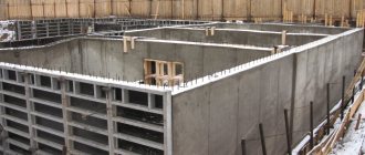
Column and strip foundations for a house or fence, external walls of a building and internal partitions - all this requires the construction of a structure made of vertical panels fixed with spacers. Installed in two rows (with the exception of square formwork for a columnar foundation), the boards or sheets of plywood are rigidly attached so that they can be easily dismantled later. The simplest option for connecting shields is tin ties and internal struts made of thin timber.
Before calculating the formwork for the foundation or walls, measure the perimeter of the future structure as accurately as possible. Then determine the height to which the structure will need to be erected, usually this is the height of the foundation or wall plus 20 centimeters. Next, if we make the sides for pouring from boards, we need to find out how many cubic meters of lumber will be needed. To do this, we multiply the double perimeter by the height of the formwork and by the thickness of the board. We obtain a formula of the form V = 2 PHn , where n is the thickness of the lumber. To find out how many materials are needed in pieces, we multiply the double perimeter by the height of the side, and then divide by the area of the board s, according to the formula 2 PH/ s .
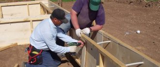
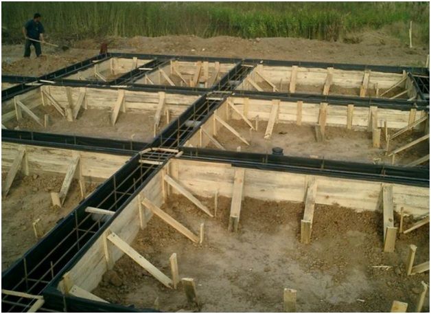
It is most practical to make shields while digging a pit or trenches for the foundation; this will save you a lot of time
. To do this, you will need several sheets of 18 mm plywood with dimensions of 1525x1525 mm, sawn in half (the amount of material depends on the length and height of the formwork). Along the perimeter of each trim we nail a 50x50 millimeter beam with five-centimeter nails, driving them in from the plywood side. A crossbar made of another block is attached in the middle. In the longitudinal and end parts of the frame, holes with a diameter of 13 millimeters are drilled for a bolted connection, with the help of which the structure will be assembled from ready-made panels.
In addition to shields, you will need, as mentioned above, tin ties, unless, of course, you plan to build complex wooden restrictive fastenings. For each shield you need to prepare 4 ties - two at the top and two at the bottom. If the formwork is built in a single row, then the lower tin elements will remain in the concrete and will simply be cut off, and the upper ones can be used more than once. If the structure is planned to be multi-row, for pouring walls, then only the very top ties will be removable. In addition, as spacers for each shield you will need two short bars, the length of which must correspond to the thickness of the foundation or wall. As the concrete is poured, the bars are removed.
Scope of application of formwork on vehicles
The use of this type of formwork is allowed when pouring a floor that rises no more than 4.5 meters above the floor and weighs less than 7 tons. In structures with large values for these indicators, volumetric beams are used. Telescopic racks are relevant in low-rise construction; with their help, you can avoid the cost of consumables (boards, roofing felt, slats, etc.).
To create formwork on a vehicle, a set of parts is required, which is most often purchased as a kit. Each of the assembly parts has its own characteristics and parameters, so it is important to choose the right kit for the implementation of the planned construction project. It is important to note that using this type of formwork you can create systems of various sizes and shapes.
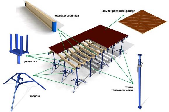
A set of parts required to create formwork on a vehicle
How are load-bearing beams and frames calculated?
The role of the supporting structure for the formwork panels is performed by a system of special I-beams. They can be made of laminated veneer lumber or metal. It is advisable to use metal beams in the manufacture of massive floors of great length and thickness. As with the installation of other elements of the formwork system, when laying beams, one should rely on the expected static and dynamic loads. In the process of calculation work, take into account the mass of panels, concrete pouring, reinforcing belt, as well as construction equipment and working personnel. The distance between each beam must be sufficient to prevent deck deflection and ensure uniform mass distribution.
Features of calculating the amount of materials
The average cost of such a kit can reach 40 thousand rubles (without fasteners). To calculate the size of the formwork, it is recommended to use certain formulas.
So, using the formula Kst 300cm = B/3, the number of rack elbows is calculated to create the required height, the value of which is three meters.
There is another formula: B = B1 – Vb – Vuv – Vo. In it, B is the total height of the structure, B1 is the gap between the ceiling and floor covering, Wb is the height of the beam (a common value is 40 cm), Vuv is the length of the universal beam and Vo is the length of the support (the value is 50 centimeters).
In addition to determining the height, calculations must be carried out to determine the required number of axes. In this case, the following technique is used: Ko = (W/D+1)*(D/Dr+1). In the formula, W is the width of the area, D is its length, DR is the length of the crossbar. The number of supports and uniforks is calculated in a similar way.
A similar formula is used to determine the required number of crossbars per tiers for formwork:
Kr (number of crossbars) = (W/Dr)(D/Dr+1) + (W/Dr+1)(D/Dr).
To determine the number of tiers, calculations are carried out using the following method: Kar = Ks+1, in this case Ks denotes the number of racks.
Each rack will require a tier of crossbars of the fastening type +1. If the axle includes two posts, the length of which is 2.5 m, to fix it, three tiers will be required with fasteners mounted in the center and at the ends.
To determine the required number of inserts, use the following calculation method: Chv = Chvo – 1, Chvo here means the number of racks on each axis. Each rack must be fastened using inserts. They may not be used where forks and supports are placed.
You can determine the length of the beam and the required size of plywood using the first of these formulas. The thickness of the material depends on the thickness and weight of the ceiling. When installing the formwork, for safety reasons, reinforcement of the plywood is required; for this, it is fixed to the beam using self-tapping screws.
Thanks to the formulas, the master will be able to calculate the costs of materials and determine their volume. However, for accurate results, it is recommended to contact professionals who calculate the formwork without errors.