Engineering design of houses helps to develop solutions for the placement of heating, water supply, sewerage, ventilation and electrification connections in future buildings.
It is at this stage that the distance from the water supply to the foundation is established, which is so necessary to ensure safe and comfortable living in the house.
Depending on the nature of the water supply, centralized and autonomous utility network systems are determined. They are united by the single requirement of SNiP 2.07.01–89, on the minimum possible distances when laying pipes from the external boundaries of the foundation of the house. According to this regulation, all underground trenches of utility networks, be it water supply or sewerage, are located outside the area of high pressure of the building, thereby helping to protect the foundation from erosion in the event of a pipe break. Also, compliance with SNiP regulations allows for access to pipes for repairs.
Distance from water supply to foundation and sewerage - requirements and standards
The functionality of a residential building and the convenience of living in it are ensured by the connection of water supply and sewerage networks to the building. Depending on the ownership of the sources of water supply and wastewater disposal, utility networks can be classified as centralized or autonomous systems. But their specificity in no way affects the permissible distance of the pipes being laid from the foundation of the building, which the regulatory documentation requires to maintain. In particular, SP 42.13330.2011, which is an updated version of SNiP 2.07.01-89*, provides the minimum setbacks for external water supply and sewerage systems from the side walls of the foundation of both the house and various fences, as well as power poles. Of course, these rules have nothing to do with releases.
If there are communications on the site
When the location of the site is such that underground communications pass through it, then a certain distance must also be maintained to them. The distance of the cesspool depends on the type of pipes:
- Asbestos-cement or reinforced concrete - from 5 meters.
- Cast iron with a diameter of up to 20 cm - 1.5 m.
- Cast iron with a diameter of more than 20 cm - from 3 m.
- Gas pipes – from 5 meters.
Important! When moving pipes away from the cesspool on a site, you should be guided by the rule, the farther the better.
Requirements
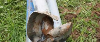
All standards covering the construction sector are developed taking into account the safe operation of structures and utility networks. This condition applies to the structures themselves, as well as to the environment and people. As for water supply and sewerage, an unfavorable factor can be a breakthrough or depressurization of pipe joints with subsequent flooding of the area, erosion of the soil base and destruction of the foundation.
If communications are located too close, in the event of an emergency, water will not have time to seep into the soil before it reaches the foundation walls. With sewage, the situation is even worse. An environment with a high acid content can negatively affect the waterproofing layer, and from a sanitary point of view nothing good can be expected. Another “surprise” will be the difficulty of opening the pipeline to ensure its repair or replacement. In such a situation, it will be necessary to expose the foundation, which is not always possible.
In situations where the required distance from the networks to the house cannot be maintained for some reason, water supply and sewerage pipes can be laid in casings. This decision is made after expert assessment and agreement with the relevant services of the local Vodokanal.
The length of the cases is selected taking into account that the edges of the laid protective pipes protrude beyond the boundaries of the security zone specified in the SP.
Punishment for non-compliance
They are punished for violating the rules for the location of cesspools and street toilets with a ruble, that is, they issue a fine. Its size depends on several factors:
- Have any cases of violation of environmental legislation by a citizen been previously recorded?
- How badly the norms have been violated. This means that if the cesspool is closer than necessary to the foundation of the house, the fine will be less than if a potentially dangerous object is located closer than 20 meters from a source of drinking water.
The specific amount of punishment is determined by the court; it is in court that the measure of punishment for such an offense is determined. Violation of environmental standards is dangerous for many people, so fines amount to thousands of rubles.
Placement of water supply and sewerage
When laying underground communications, it is necessary to proceed from regulatory requirements. They, among other things, indicate the minimum horizontal clear distance from the pipe to the existing foundation of the house:
- for water supply – 5 meters;
- for pressure sewerage – 5 meters;
- for domestic sewerage (gravity flow) – 3 meters;
- for rainwater drainage – 3 meters;
- for drainage networks – 3 meters;
- for accompanying drainage - 0.4 meters.
In cramped conditions, the distance from communications to the edge of the foundation can be reduced to 1.5 meters, but only in cases where steel or polymer pipes are used for water supply, and pressure cast iron pipes are used for sewerage. In this case, they will have to be laid in a casing at a level above the level of the foundation base by half a meter.
When installing communications in conditions of subsidence and permafrost soils, the distance from the foundation of the house to the pipelines can be increased. This decision is made at the stage of linking the construction project to specific geological conditions. In some cases, it is possible to reduce the distance, but such a decision must have appropriate justification.
Distance to the fence foundation:
- for water supply and pressure sewerage - at least 3 meters;
- for domestic and rainwater drainage – at least 1.5 meters;
- for drainage - at least 1 meter.
The following horizontal distances are provided to the base of overhead power line supports:
- up to 1 kV – 1 meter;
- up to 35 kV – 2 meters;
- over 35 kV – 3 meters.
The standards also provide the minimum distances of pipelines from the axis of a tree trunk with a crown of no more than 5 meters in diameter. For the sewer network, the horizontal dimension is 1.5 meters, and for the water supply and drainage network - 2 meters.
No less important is the location of utility networks relative to each other. For water supply, a higher level of installation is always chosen than for sewerage. This is especially true for the intersection of two pipelines, which must be done at right angles. The minimum vertical distance should be 0.4 meters.
If for some reason water pipes are laid below the sewer network, they must be protected with a casing.
The pitch of parallel water supply branches is allowed to be 1.5 meters, and sewer branches - 0.4 meters. The distance between the sewer and the water supply in the plan is set depending on the diameter and material of the pipes. It is 1.5-5 meters.
Methods for laying underground networks
Laying underground communications
There are three ways to lay utility networks underground when developing a site.
- Separate method. Accordingly, each communication system is installed in the ground separately from the others, regardless of the timing of their installation. The method has a significant drawback: increased excavation work, as well as the possibility of damage to neighboring communications during opening.
- Collaborative method. Several communications for different purposes are laid in a single trench. Reduces the amount of excavation work by up to 40%.
- Combined collector. Networks for different purposes are located in a single collector. This method allows you to carry out work on laying networks, even after the completion of the zero construction cycle.
All methods are carried out in strict compliance with building codes and sanitary regulations.
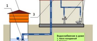
Well location
Owners often use water intake wells or boreholes to provide their home and property with water in the absence of centralized main water supply networks. In this case, it is necessary to build an autonomous sewer system. To install wells, you need to choose a convenient place, but you should not forget about the standard distances between the point of drinking water intake and the septic tank - your own or a neighbor’s. This warning concerns sanitary rules.
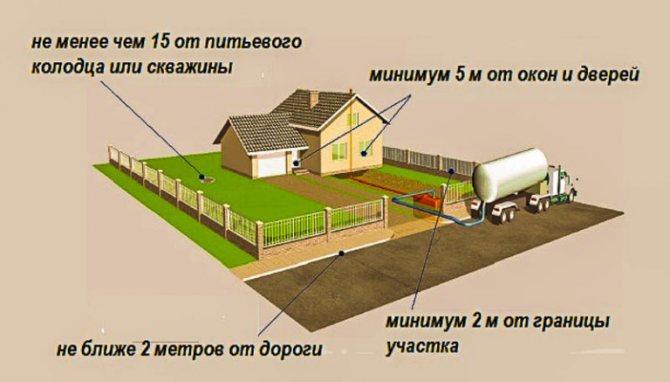
The water intake structure, intended for the autonomous supply of water to the estate, must be located in a “clean” area not far from the house. In this case, it is required to maintain a distance of at least 50 meters from potential sources of infection:
- cesspools;
- landfills;
- septic tanks;
- outbuildings intended for storing fertilizers in the form of manure or chemicals;
- sheds for livestock;
- car wash places, etc.
Only in some cases is it possible to reduce the distance to 20 meters.
Water intake wells and boreholes should not be constructed in areas that are swampy or flooded during floods. It is not recommended to install them near roads with heavy traffic. Compliance with the above rules will allow you to obtain clean drinking water, free of contamination.
Despite the fact that wells, when installing an autonomous water supply, can be brought closer to the underground part of the building at a distance of up to 3 meters, one should take into account the fact that shallow foundations do not respond well to such a proximity. The correct solution in this case would be to increase the distance between objects to the maximum possible length - up to 15 meters.
Methods for laying sewers
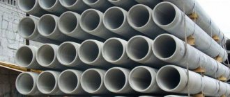
Tunnel for sewer pipes
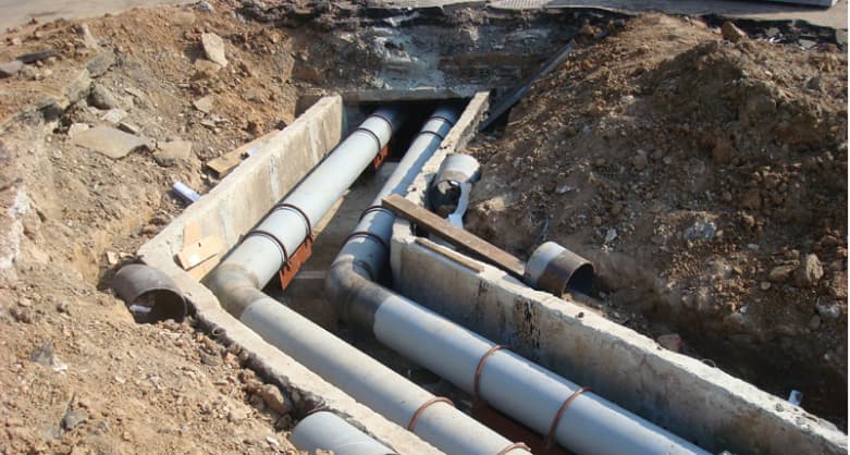
There are two ways to organize communication networks. The first involves the installation of each pipeline in its own trench, and with the second, all lines are laid in an organized tunnel, the walls and coating of which are made of prefabricated or monolithic reinforced concrete. The trench method increases the labor intensity of the work, while individual branches are dug up for repairs and maintenance. The second method is characterized by installation speed, reliable protection and quick access.
Trenches or reinforced concrete penetrations are made in such a way that the rules for placing pipes in them are observed:
- water supply networks are located above sewer collectors, the height distance is at least 0.5 meters;
- intersections are arranged perpendicularly to prevent contamination of drinking water by wastewater;
- if the water pipes are located below or at the level of the drain collectors, a casing is put on them;
- separate storm and domestic sewage systems.
If there is no central water supply, the owners drill wells, install wells, and run pipes to the house from them. The distance from the water supply to the sewerage system in the case of local use is also regulated by sanitary rules. Liquid intake sites are arranged in such a way as to withstand regulatory requirements for distance from their own and neighboring contaminated sites. These include animal pens and cattle sheds, storage areas for chemical fertilizers and manure.
Maintain a distance from them to a well or well according to the rules of at least 50 meters. If the site conditions are cramped, this gap is reduced to 20 m. The possibility of reduction is confirmed by documents VSN 61-1989 and SP 42.13.330-2011, and it is stipulated that such a technological solution should not violate the reliability of the structure and the safety of the well.
Water is usually obtained from the highest place in the yard so that neighboring and own cesspools and septic tanks are located below this area.
Underground placement of NVC networks (distances from pipelines to ...)
When designing external water supply and sewerage networks, it is preferable to provide for an underground method of placing communications.
In climatic zones with the presence of permafrost soils, water supply, sewer and drainage pipelines should be placed in the zone of temperature influence of heating pipelines.
It is allowed to place flammable and combustible liquids in common channels and pipeline tunnels together with pressure pipelines of water supply (except fire-fighting) and pressure sewerage.
Underground utilities should be placed parallel in a common trench; at the same time, the distances between utilities, as well as from communications to the foundations of buildings and structures, should be taken as minimally acceptable, based on the size and placement of cameras, wells and other devices on these networks, the conditions of installation and repair of networks.
The horizontal (clear) distances from the nearest underground utilities to buildings and structures should be taken no less than those indicated in Table 6.
| Network engineering | Distance, m, horizontally (clear) from underground networks to | ||||||||
| foundations of buildings and structures | foundations of enterprise fences, overpasses, overhead contact and communication supports, railways | extreme path axis | side stone of a street, road (edge of a roadway, reinforced roadside strip) | the outer edge of a ditch or the bottom of a road embankment | foundations of overhead power transmission line supports | ||||
| 1520 mm gauge railways, but not less than the depth of the trenches to the base of the embankment and the edge of the excavation | 750 mm gauge railways and trams | up to 1 kV of outdoor lighting, contact network of trams and trolleybuses | St. 1 to 35 kV | St. 35 to 110 kV and above | |||||
| Water supply and pressure sewerage | 5 | 3 | 4 | 2,8 | 2 | 1 | 1 | 2 | 3 |
| Gravity sewerage (domestic and rainwater) | 3 | 1,5 | 4 | 2,8 | 1,5 | 1 | 1 | 2 | 3 |
| Drainage | 3 | 1 | 4 | 2,8 | 1,5 | 1 | 1 | 2 | 3 |
| Associated drainage | 0,4 | 0,4 | 0,4 | 0,4 | – | – | – | – | |
| Gas pipelines of flammable gases pressure, MPa (kgf/sq.cm): | |||||||||
| low to 0.005 (0.05) | 2 | 1 | 3,8 | 2,8 | 1,5 | 1 | 1 | 5 | 10 |
| average over 0.005 (0.05) to 0.3 (3) | 4 | 1 | 4,8 | 2,8 | 1,5 | 1 | 1 | 5 | 10 |
| high: | |||||||||
| over 0.3 (3) to 0.6 (6) | 7 | 1 | 7,8 | 3,8 | 2,5 | 1 | 1 | 5 | 10 |
| over 0.6 (6) to 1.2 (12) | 10 | 1 | 10,8 | 3,8 | 2,5 | 2 | 1 | 5 | 10 |
| Heating network: | |||||||||
| from the outer wall of the channel, tunnel | 2 (see note 3) | 1,5 | 4 | 2,8 | 1,5 | 1 | 1 | 2 | 3 |
| from the shell of the channelless laying | 5 | 1,5 | 4 | 2,8 | 1,5 | 1 | 1 | 2 | 3 |
| Power cables of all voltages and communication cables | 0,6 | 0,5 | 3,2 | 2,8 | 1,5 | 1 | 0,5* | 5* | 10* |
| Channels, communication tunnels | 2 | 1,5 | 4 | 2,8 | 1,5 | 1 | 1 | 2 | 3* |
| External pneumatic garbage chutes | 2 | 1 | 3,8 | 2,8 | 1,5 | 1 | 1 | 3 | 5 |
| Engineering Communication | Horizontal distance (clear), m, from underground utilities to | ||||||||
| foundations of buildings and structures | fencing foundations, gallery supports, pipeline overpasses, contact networks and communications | track axis of 1520 mm gauge railways, but not less than the depth of the trench to the base of the embankment and excavation | tram track axes | ||||||
| 1 Water supply and pressure sewerage | 5 | 3 | 4 | 2,75 | |||||
| 2 Gravity sewerage and drains | 3 | 1,5 | 4 | 2,75 | |||||
| 3 Drains | 3 | 1 | 4 | 2,75 | |||||
| End of table 6 | |||||||||
| Engineering Communication | Horizontal distance (clear), m, from underground utilities to | ||||||||
| roads | foundations of overhead power transmission line supports | ||||||||
| side stone, edge of the roadway, reinforced shoulder strip | the outer edge of the ditch or the bottom of the embankment | up to 1 kV and outdoor lighting | St. 1 to 35 kV | St. 35 kV | |||||
| 1 Water supply and pressure sewerage | 2 | 1 | 1 | 2 | 3 | ||||
| 2 Gravity sewerage and drains | 1,5 | 1 | 1 | 2 | 3 | ||||
| Note It is allowed to provide for the laying of underground utilities, with the exception of fire-fighting water supply and gas pipelines of flammable and toxic gases, within the foundations of supports and overpasses of pipelines, galleries, and contact networks, provided that measures are taken to exclude the possibility of damage to communications in the event of settlement of foundations, as well as damage to foundations in an accident on these communications. | |||||||||
The horizontal (clear) distances between adjacent underground utilities when they are placed in parallel should be taken no less than those indicated in Table 7, SP 18.13330.2011.
| Table 7 | ||||||||||||
| Engineering Communication | Horizontal distance (clear), m, between | |||||||||||
| running water | sewerage | drainage or gutters | gas pipelines for flammable gases | |||||||||
| low pressure up to 0.005 MPa | average pressure St. 0.005 to 0.3 MPa | high pressure St. 0.3 to 0.6 MPa | ||||||||||
| 1 Water supply | 1,5 | (See note 1) | 1,5 | 1 | 1 | 1,5 | ||||||
| 2 Sewerage | (See note 1) | 0,4 | 0,4 | 1 | 1,5 | 2 | ||||||
| 3 Drainage and wastewater | 1,5 | 0,4 | 0,4 | 1 | 1,5 | 2 | ||||||
| * In accordance with the requirements [14]. Notes 1 The distances from the sewerage system to the drinking water supply should be: to the water supply system made of reinforced concrete and asbestos-cement pipes laid in clay soils - 5 m, in coarse and sandy soils - 10 m; to a water supply system made of cast iron pipes with a diameter of up to 200 mm - 1.5 m, with a diameter of more than 200 mm - 3 m; to the water supply system made of plastic pipes - 1.5 m. The distance between the sewerage and industrial water supply pipelines, regardless of the material and diameter of the pipes, as well as the nomenclature and characteristics of the soil, must be at least 1.5 m. 2 When two and more than gas pipelines of flammable gases, the clear distances between them should be for pipes with a diameter of: up to 300 mm - 0.4 m; more than 300 mm - 0.5 m. 3 The table shows the distances to steel gas pipelines. The placement of underground gas pipelines made of non-metallic pipes should be provided in accordance with the set of rules for the design of internal and external gas supply devices. | ||||||||||||
| End of table 7 | ||||||||||||
| Engineering Communication | Horizontal distance (clear), m, between | |||||||||||
| gas pipelines and flammable gases | power cables of all voltages | communication cables | heat pipes | canals, tunnels | ||||||||
| high pressure St. 0.6 to 1.2 MPa | outer wall of a channel, tunnel | ductless laying shell | ||||||||||
| 1 Water supply | 2 | 0,5* | 0,5 | 1,5 | 1,5 | 1,5 | ||||||
| 2 Sewerage | 5 | 0,5* | 0,5 | 1 | 1 | 1 | ||||||
| 3 Drainage and wastewater | 5 | 0,5* | 0,5 | 1 | 1 | 1 | ||||||
When crossing utility lines, the vertical (clear) distances must be no less than:
a) between pipelines or electrical cables, communication cables and railway and tram tracks, counting from the base of the rail, or highways, counting from the top of the coating to the top of the pipe (or its case) or electrical cable - based on the strength of the network, but not less than 0 .6 m;
b) between pipelines and electrical cables placed in canals or tunnels and railways, the vertical distance, counting from the top of the canals or tunnels to the bottom of the railway rails, is 1 m, to the bottom of the ditch or other drainage structures or the base of the railway earthen embankment canvas - 0.5 m;
c) between pipelines and power cables with voltage up to 35 kV and communication cables - 0.5 m;
d) between power cables with a voltage of 110-220 kV and pipelines - 1 m;
e) in the conditions of reconstruction of enterprises, subject to compliance with the requirements (Rules for the construction of electrical installations PUE), the distance between cables of all voltages and pipelines can be reduced to 0.25 m
f) between pipelines for various purposes (with the exception of sewer pipelines crossing water pipelines and pipelines for toxic and foul-smelling liquids) - 0.2 m;
g) pipelines transporting drinking water should be placed 0.4 m higher than sewer or pipelines transporting toxic and foul-smelling liquids;
h) it is allowed to place steel pipelines enclosed in cases transporting drinking water below sewer pipes, while the distance from the walls of the sewer pipes to the edge of the case must be at least 5 m in each direction in clay soils and 10 m in coarse and sandy soils , and sewer pipelines should be made of cast iron pipes;
i) utility and drinking water supply inlets with a pipe diameter of up to 150 mm may be provided below sewer lines without installing a casing, if the distance between the walls of intersecting pipes is 0.5 m;
j) when laying ductless pipelines for water heat pipelines of an open heating or hot water supply system, the distance from these pipelines to the sewer pipelines located below and above should be taken as 0.4 m.
Intersections of pipelines with railway and tram tracks, as well as with roads, should, as a rule, be provided at an angle of 90°. In some cases, with appropriate justification, it is possible to reduce the intersection angle to 45°.
The article was written on the basis of SP 18.13330.2011, section 6.
Passage of sewer pipes through the foundation
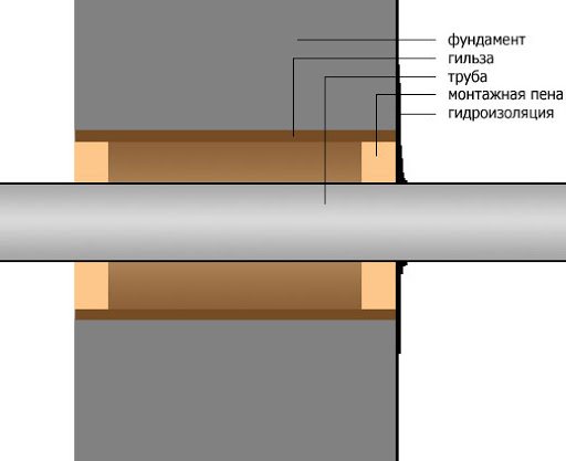
Pipe passage through the foundation
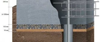
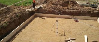
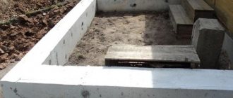
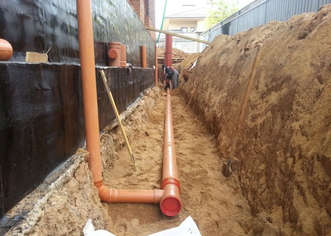
The installation of the sewer system is done through a sleeve with a diameter of 150 mm, which is previously placed in the body of the foundation when pouring concrete. A check valve is provided on the pipeline to prevent waste from flowing into the interior. The trench is dug at the depth of the soil freezing mark according to local standards.
A sand bedding about 15 cm thick is placed at the bottom of the ditch to maintain the tightness of the main line when the soil is moving. Sewerage is laid without taking into account freezing if there is a high level of soil liquid in the region. In this case, the external sewerage system and the place where it passes through the base of the house are insulated and waterproofed.
The sewer is pressed and identified leaks are eliminated. The passage area is sealed with polyurethane foam. The walls of the cesspool are finished with bricks at intervals or made of concrete rings. The distance from the foundation to the septic tank well is maintained according to sanitary standards.
If the sleeve was not laid during concreting of the base, the foundation is drilled using a hammer drill and a jackhammer. Any fittings that come across are cut with a grinder. A sleeve is inserted into the resulting hole.
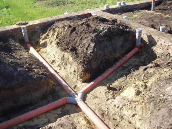
Sometimes they dig under a strip foundation to lay a pipe, so as not to reduce the bearing capacity of the foundation. The location of the trench is calculated precisely so that the axes of the internal and external collectors coincide. A pipe is placed under the foundation, the cross-section of which exceeds the diameter of the sewage networks. Backfilling is done carefully so as not to displace the laid areas.
If there is not enough space
It happens that those responsible for violating sanitary standards make excuses by saying that there is not enough space, and that is why they violated the rules. But in fact, it is possible to install a toilet correctly or arrange a cesspool. If, according to the standards, there is not enough space on the site, the solution is to construct a pit using a sealed container. There are also septic tanks and other installations that can be mounted on the surface, they are also sealed.
Of course, such solutions are more expensive than a cesspool, but by not complying with SNiP standards, the owner of the site primarily harms himself. It pollutes water and makes the soil unsuitable for growing any vegetables, trees, and shrubs.
Compliance with sanitary standards regarding the placement of a cesspool and the location of the toilet according to SNiP in the country is very important. Violation is fraught not only with fines, but also with harm to one’s own health.
Information about mining territories
The design of sewerage networks in mined areas must be carried out on the basis of a mining and geological justification, taking into account the maximum calculated values of the expected deformations of the earth's surface. In the process of routing networks, it is necessary to provide for the following measures that can ensure the removal of wastewater from the territory in the event of an accident:
- The ability to transfer water from one collector to another.
- Use pipes of minimal length - asbestos-cement, ceramic, reinforced concrete.
- Making butt joints flexible, elastic, capable of absorbing longitudinal and angular mutual movements of pipe ends in the event of deformation of the earth's surface.
- Laying pipes in impassable parts of the territory in case of opening during periods of intense deformation.
- Laying two lines that will operate in parallel if it is necessary to use pipelines that have a diameter of more than 600 mm.
Ceramic pipes that have a diameter of up to 300 mm must be laid with a gap of 6 mm, more than 300 mm - with a gap of 8 mm. Reinforced concrete and asbestos-cement pipes with a length of up to 3 meters - with a gap of 15 mm, for longer lengths - 20 mm.
The joints of socket pipes are sealed using asbestos cement, which is reinforced with metal wire, and rubber rings.
For pressure pipelines in areas of 1-3 groups of workings, it is necessary to use steel pipes with the installation of compensators, and in areas of 4 groups - asbestos-cement, reinforced concrete and plastic. On pipelines that have a diameter of up to 500 mm, it will be necessary to install expansion joints with eversible cuffs that allow horizontal and angular displacements without violating the tightness.
For objects located in mined areas, it is not allowed to design all-alloy sewerage systems. It is necessary to coordinate such projects with local bodies of Gosgortekhnadzor and organizations that operate deposits.
Choosing a sewer installation location
In private homes, it is mandatory to install a purification device, whose task is to remove contaminated water. Separate sewerage means two trenches for the removal of wastewater: a storm water inlet and a domestic drain. Sewer pipes with a cross-section of less than 50 mm are buried 30 cm from the level where the soil reaches zero temperature. From 50 mm and more require a half-meter deepening below the depth of soil freezing.
The layout of pipelines and the location of wells for sewerage are thought out in advance. For rational placement of the septic tank, it is important to decide on the location of the water intake well, and also not to forget about all the distances recommended by SNiPs and sanitary standards. Sewage wells are capital structures for long-term operation. If initially installed in the wrong place, it is almost impossible to move them.
This approach to the construction of drainage systems allows us to reduce the risks of emergency situations, leaks and stagnation of wastewater. When planning, you need to consider:
- distance between nearby highways;
- remoteness from one's own and neighbors' buildings;
- distance to the street and highway;
- sewer pipe section;
- location of aquifers.
When placing a septic tank, be sure to take into account the prevailing wind direction during the year so that others do not suffer from an unpleasant odor.
To accurately determine the depth and location of underground communications, proceed in the following order:
- Draw up an accurate plan of all highways, taking into account the standards specified in SNiPs.
- Double-check that the design data matches the graphical diagrams or drawings.
- Before laying new communication lines, check whether there are old pipelines or sections of the electrical network at their location.
All these actions will help prevent problems with damage to the electrical cable if it is present at the pipe laying site, as well as not break existing lines in order to avoid emergency situations.