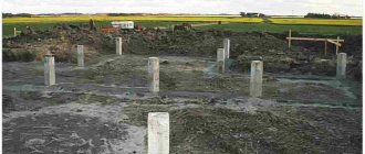
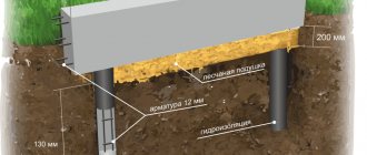
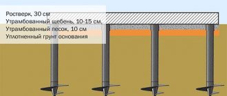
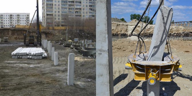
Piles are special rods made of metal, concrete or wood, which are buried in the ground when constructing the foundations of various buildings.
The use of piles is advisable in cases where the upper layers of soil, for various reasons, cannot serve as a natural foundation for resting building foundations on them.
Calculating the number of screw piles using a calculator
- Specify the length of the sides of your building, choosing a shape from 3 to 15 meters.
- Indicate the type of building - house, garage, household building, etc.
- Indicate “number of floors” if the corresponding columns appear. When filling out the columns, please note that a house with an attic will be considered a one and a half-story building.
- Choose the material for your building.
- Indicate the type of soil on the site.
- Indicate the number of corners of the planned house.
- Specify the height of the basement floor from the proposed options.
- Please indicate whether you are going to install a fireplace/stove.
- Click “Calculate”.
In a few seconds, the result of calculating the required number of piles for your object will appear.
Let's look at an example
There is a peat area with a peat depth of 3 meters. You have decided to build a wooden house (timber 150x150), with an area of 10 by 10 meters. The house is planned to have an original shape with nine corners and an attic. The floor will be located at a height of 50 cm above the ground. To keep you warm in winter, it was decided to install a fireplace in the house.
After all the data was entered, the calculator for calculating the number of screw piles gave us the result - 32 piles, with a diameter of 108 mm and a length of 4.5 meters.
Of course, this calculation is preliminary. It serves as a guide when planning your budget and further orders. For a more accurate result, it is necessary for a specialist to visit the site for a detailed inspection of the site for the planned development, where all factors will be taken into account.
Calculation of pile foundation settlement
Calculation of settlements of foundations on rack piles is not carried out, since they transfer the load to a practically incompressible or low-compressible base. The amount of settlement of a pile foundation made of piles pinched in the ground is determined by calculation using the limit states of the second group.
It is recommended to calculate foundations made from pile fields larger than 10´10 m using the linear deformable layer scheme. In this case, the dimensions of the conditional foundation are taken equal to the size of the grillage in plan, and the calculation is made using the average pressure on the base in the plane of the base of the slab grillage, increasing the calculated thickness of the layer by an amount equal to the depth of immersion of the piles, and taking the deformation modulus of the layer cut by the piles equal to infinity or modulus of elasticity of the pile material.
In other cases, settlement calculations are recommended to be performed using the layer-by-layer summation method. The boundaries of the conditional foundation are shown in Figure 2.4. The vertical edges of the conditional foundation are spaced from the outer edges of the outermost rows of piles at a distance
,
where h is the length of the part of the pile in contact with the ground; φII,m – weighted average value of the angle of internal friction of soils cut by piles;
jII,i – calculated values of the angle of internal friction for individual layers of soil cut through by a pile, thickness hi.
This is due to the fact that due to friction along the lateral surface between the pile shaft and the soil, part of the soil is also involved in joint work and can be considered as part of the foundation.
Thus, the dimensions of the conditional foundation will be determined by the formulas:
,
where b and l are the distances between the outer edges of the outer rows of piles along the width and length of the foundation, m.
The calculation is carried out in the same sequence as for a foundation on a natural foundation. The stresses at the base of a conditional massive foundation are determined in the same way as for a foundation on a natural foundation under the influence of No1 and the own weight of the conditional foundation, which includes the weight of the grillage, the weight of the piles and the weight of the soil within the volume abcd (see Figure 2.4).
The settlement value obtained by calculation should not exceed the limit value determined according to Table 1.16 or Table B.1 [1].
Calculations of the pile foundation are completed with the selection of pile-driving equipment. You can use the technique described in the reference literature [2, p. 207-210].
Example . We check the ground pressure from the conditional foundation ABCD (Figure 2.5). Let us determine the weighted average value of the angle of internal friction jII,m and the dimensions of the base of the conditional foundation ly and by, taking into account that the distance between the outer edges of the outer rows of piles b0 = 2.3 m and l0 = 3.5 m:
jII,m = SjII,ihi/Shi = (16×8+18×3.2)/(8+3.2) = 16.5°;
by = b0 + 2 htg(jII,m/4) = 2.3+2tg(16.5/4) = 3.85 m;
ly = l0 + 2 htg(jII,m/4) = 3.5+2tg(16.5/4) = 5.05 m.
Conditional array weight
Ny=bylySgIIihi= 3.85×5.05(16×1.2 + 19×1.3 + 19×2.2 + + 10×2.2 + 18×3.2)=6225 kN.
Total pressure under the base of a conditional foundation
pII = (NoII+Ny)/(byly) = (6275 + 6225)/(3.85 × 5.05) = 643 kPa.
The calculated soil resistance R under the base of the conditional foundation will be determined by formula (B.1) [1], taking d = dy and b = by and taking into account that gс1 = 1.25; gс2 = 1; k = 1; kz = 1; My = 0.43; Mq = 2.73; Mc = 5.31 (for jII = 18° load-bearing layer); b = 3.85 m; gII = 18 kN/m3 – specific gravity of the soil located under the base of the conditional foundation; d = 17 m; сII = 30 kPa – adhesion of the load-bearing soil layer; = (16×1.2+19×4.8+19×8+18×3)/(1.2+4.8+8+3)= = 18.6 kN/m3 – weighted average value of the specific gravity of the soil within the depth of laying a conditional foundation;
Checking the ground pressure at the base of the foundation
р = 643 kPa < R = 1315 kPa.
The requirement of clause 5.10 of SNB 5.01.01-99 has been satisfied. Settlement calculations can be performed using elasticity theory solutions. Since the width of the foundation is less than 10 m, the layer-by-layer summation method can be used.
Figure 2.5 – Calculation scheme for determining foundation settlement
Natural pressure at the level of the base of the conditional foundation
Additional pressure along the base of the conditional foundation
We determine natural and additional stresses in the base (Table 2.6) and construct diagrams of these stresses (see Figure 2.5) at h = ly/by = 5.05/3.85 = 1.31 and hi = 0.4b = 0, 4×3.85 = 1.54 m.
|
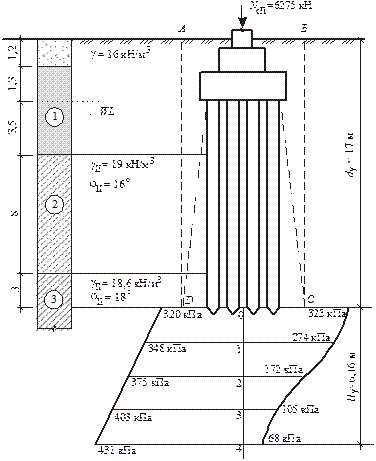
Table 2.6 – Determination of natural and additional pressures
| Layer boundary number | Priming | z, m | x = 2z/b | a | szg, kPa | szр, kPa | szр,ср, kPa |
| Clay E=19 MPa | 1,000 | ||||||
| 1,54 | 0,8 | 0,848 | |||||
| 3,08 | 1,6 | 0,532 | |||||
| 4,62 | 2,4 | 0,325 | |||||
| 6,16 | 3,2 | 0,210 | |||||
| Sszр,ср= |
The calculation of foundation settlement is determined by the formula
The resulting foundation settlement value is less than the maximum permissible foundation settlement su = 8 cm for buildings with a reinforced concrete frame.
2.8 Principles of calculation of horizontally loaded pile foundations
The foundations of a number of structures (bridge supports, overpasses, overpasses, etc.) may experience horizontal loads comparable in magnitude to vertical ones. The calculation of such foundations includes two stages: the first - for vertical load, as described above, and the second - checking the pile for the combined action of vertical and horizontal loads.
The static calculation of single piles comes down to the fact that the pile is considered as a beam having given dimensions and given loads at one end, on an elastic Winkler foundation, characterized by a bed coefficient that increases linearly with depth.
Based on solutions of structural mechanics, formulas were obtained to determine the horizontal displacement of the pile at the level of the base of the grillage u and the angle of its rotation y, the design pressure s exerted on the ground by the side surfaces of the piles, as well as to determine the bending moments M and transverse forces Q in various sections along the length piles. The calculation sequence includes:
a) calculation of piles based on deformations, which boils down to checking the conditions for the admissibility of the calculated values of the horizontal movement of the pile head and the angle of its rotation:
u < uu; y < yu,
where uu and yu are the maximum permissible values, respectively, of the horizontal movement of the pile head, m, and the angle of its rotation, rad, established in the design assignment for the structure;
b) calculation of the stability of the foundation soil surrounding the pile (only for piles with d > 0.6 m), which consists of comparing the design pressure s with the bearing capacity of the soil;
c) checking the strength of piles as eccentrically compressed elements, the resistance of the material according to the limit states of the first and second groups.
Pile foundations with inclined piles are considered as spatial statically indeterminate frame structures interacting with an elastic (Winkler) foundation. The uprights of this frame are piles, and the crossbar is a grillage. The interaction of soil and piles can be taken into account in two ways: as a rigid conditional embedding of piles in the soil or as the deformation of a flexible rod in an elastic environment. In any case, the calculation is carried out using the displacement method.
In addition, for low grillages, the resistance of the soil along its lateral surfaces is additionally taken into account.
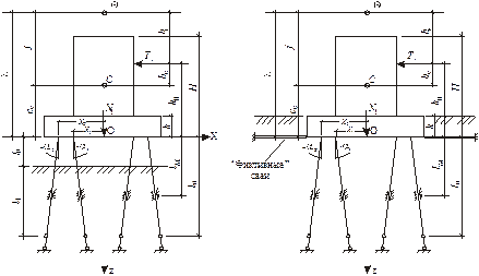
Design diagrams for high and low grillages are shown in Figure 2.6.
a) b)
Figure 2.6 – Design diagrams for pile foundations: a – with a high grillage; b – with a low grillage
To simplify the calculation, “characteristic centers” of the rod system are introduced: C – elastic center (if a force is applied at this point, it causes only translational motion of the entire system); Q is the center of zero displacement (the force passing through it perpendicular to the OZ axis causes the grillage to rotate around point O).
Calculation of forces and displacements is performed in the following order:
1 Determine the forces transmitted to the flat design diagram (design row of piles) using the formulas:
,
where is the calculated normal force at the level of the grillage base, kN; T – design horizontal load acting at a distance h0 from point O; h0 =M/F; kр – number of calculation series; M is the total moment from all forces relative to point O, acting in the design plane.
2 Calculate the relative values of unit reactions of the system using the formulas:
;
;
;
,
where ai are the projections of the pile inclination angles onto the design plane (positive when the piles deviate from the vertical axis to the left); n – number of piles in the design row; pf – number of fictitious piles (when calculating a low grillage); xi – distances from the axis passing through the center of gravity of the pile field at the level of the foundation base to the axes of the piles (positive - to the left of point O); ln – design compression length of piles, m; lм – design bending length of piles, approximately accepted; l0 – free length of the pile (for a low grillage l0 =0).
3 For a low grillage, find the number of fictitious horizontal piles using the formula
,
where Fp is the reactive pushback of the soil for a single horizontal movement of the grillage; Асв – pile cross-sectional area, m2; Eb – modulus of elasticity of the pile concrete, kPa.
The value of Fp can be determined by the formula
where b is the width of the side face of the grillage perpendicular to the plane of the design diagram, m; Eg – deformation modulus of the soil located at the side face of the grillage, kPa.
4 Determine the position of the characteristic centers C and Q using the formulas:
In this case, the condition c0 < h0 < l must be satisfied. The quantities c0, l, bQ can have both positive and negative values.
5 Calculate the relative and absolute movements of the grillage:
turn
horizontal movement
vertical movement
6 Find the horizontal displacement of the top of the foundation and compare its value with the maximum permissible:
.
7. Determine longitudinal forces and moments in the matchers using the formulas:
8. Check the load-bearing capacity of piles on the ground:
,
where Fd is the load-bearing capacity of piles on soil or material (less).
For foundations with a low grillage and vertical piles (ai = 0), the calculation formulas are significantly simplified. Longitudinal forces and moments in this case can be found using approximate formulas:
.
For a high pile grillage containing only vertical piles (пф = 0), approximate formulas will look like
.
Self-payment on site
The same calculation can be done independently and without using a calculator. The result obtained in this way is in most cases less accurate. You will need to determine the type and density of the soil, analyze the natural topography, and determine the distance at which the denser layers of soil are located.
Another option for finding out the required number of piles is to calculate them according to the plan of the first floor. Here you need to count the number of corners and joints of external walls with load-bearing partitions. The piles should be located in the indicated places; they should go along the perimeter in increments of no more than three meters. If you plan to install a fireplace, then, depending on its weight, you will need to install from one to four piles under it.
Carry out the calculation on the calculator and on the ground floor plan and compare the results.
Calculation of the bearing capacity of the pile
To calculate the load-bearing capacity of piles, various tests are first carried out:
- Statistical sensing.
- Pile testing (statistical and dynamic).
- Soil research.
The calculation is made in accordance with SNIP 2.02.03-85 “Pile foundations”.
Calculation formula
Where:
- A – transverse area of the pile;
- M – special soil category coefficient;
- Ed is the calculated energy from the hammer hitting the rod
- m1 is the mass of the impacted device;
- m2 is the mass of the rod and cap;
- m4 is the mass of the impacted element;
- Sa is the residual failure of the pile
- Sel—elastic pile failure
Application of calculations in practice
The application of calculations in practice is a very important task for the rational use of materials, as well as compliance with the safety requirements of construction production.
If you use materials of insufficient strength, you may not obtain the declared performance characteristics of the foundations. If more massive structures are unreasonably used, the result will be a significant cost overrun.
Installation of piles is a rather complex and labor-intensive procedure that must be approached very seriously. Neglecting calculations can lead to unpleasant consequences. The best solution when choosing this type of foundation is to turn to professionals.
What is called pile failure?
In general terms, pile failure is a calculated or, in practical terms, established depth mark at which it becomes difficult to drive a pile due to the composition and characteristics of the soil. Before carrying out work on the construction of a pile field, it is necessary not only to accurately determine and map out the actual location of the piles. In addition, it is important to accurately conduct geological surveys at the site and calculate the failure depth of the pile - this way it will be possible to optimally use the capabilities of the pile foundation and prevent its destruction.
The design failure of a pile is the ground level determined based on a variety of initial data at which immersion of the pile becomes problematic. Failure is measured in millimeters.
In the process of driving a pile with a hammer or pressing a pile with a special installation, two scenarios can occur: either the pile at some point will hit a solid horizon and stop going into the ground, or it will fall into the ground completely. For construction, reaching a given level is important, so preliminary determination of the design failure of a pile is extremely important for the efficiency of the entire construction.
True and false pile failure
An important concept in the production of driving works is the foundation of the pile. This is the amount by which the support is ready to sink. During the driving process, you can observe the trend in which the pile goes deeper. Typically, a mark of 10 hammer blows is used for this: the depth to which the support goes deep is noted. If the immersion is carried out by vibration, then the countdown of the deposit is determined by the time interval.
True pile failure
An important feature: work on driving the pile is carried out until the moment when it sits firmly in the ground and further driving is impossible.
False pile failure can occur due to a slow or too fast driving rhythm of the support. Also, such a delay can be caused by the characteristics of the soil layers. In any case, if the dive stops before reaching the specified calculated depth, or before the bail mark, then work should continue.
True pile failure is the ultimate goal. Thanks to design work and pre-design research, it is possible to identify this mark and it is necessary to reach it. In this case, the base receives sufficient strength and reliability.
Pile failure, defined as the planned immersion of the support to a specified depth, is critical to the success of the entire construction. The calculated failure of piles during driving must correspond to the practical one within the limits of permissible discrepancy.
False failure of piles
Simply knowing what a failure of a pile during driving is is not enough to carry out the work competently. It is important to correctly perform design calculations, because this determines the subsequent order of work.