The production of piles is concentrated in factories of reinforced concrete products (RCP), which have the necessary equipment and craftsmen.
Application area

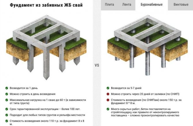
Reinforced concrete piles are convenient to use on weak soils.
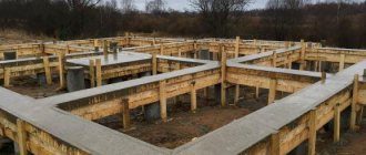
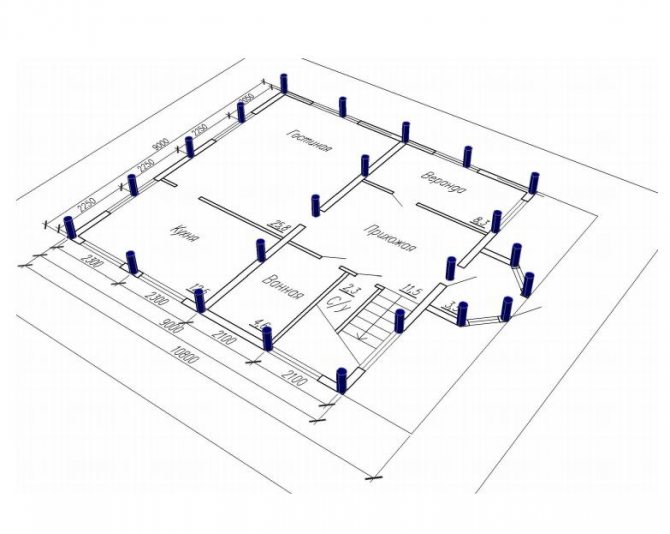
Pile foundations provide a unique opportunity to construct objects on soils with weak bearing capacity or subject to changes in physical characteristics, which include peat bogs, loess, water-saturated clays and loams, and permafrost soils.
Free-standing foundations for columns rest on a “cluster of piles,” distributing the load over several supports.
It is not recommended to use handicraft items that do not have factory quality certificates.
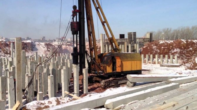
Sometimes the length of a standard pile is not enough to ensure the reliability of the foundation. In this case, composite piles are used, joined along their length. The same is done if the pile foundation is not made hanging, but supported on rocks or a horizon with high soil strength.
An embedded reinforced concrete pile can withstand loads of over 6 tons and has a high load-bearing capacity due to the contact area of the material with the soil and the creation of a local compaction zone around the element during installation.
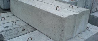
Order reinforced concrete piles size 150 by 150
If you are interested in arranging a foundation using 150*150 mm piles, please contact the specialists of our company. We are ready not only to supply reinforced concrete products, but also to perform turnkey piling work, providing you with a high-quality and reliable foundation, completely ready for further construction.
Rice . Why our clients choose our services
To order piles and their immersion, call +, +7, or use the “Leave a request” form and we will contact you and answer all your questions.
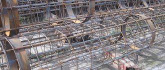
Monolithic solid piles
A metal frame is installed inside such piles.
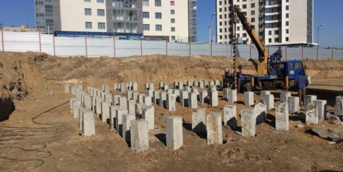
In the practice of constructing pile foundations, the dominant position is occupied by driven reinforced concrete piles or, as they are otherwise called, “submersible” piles of square or rectangular cross-section.
They are made of monolithic concrete with a reinforcement frame installed inside from rods with a diameter of 12 mm. Depending on the length, cross-section, and design load of the pile, reinforcement characteristics are selected and are produced in standard and crack-resistant versions, recommended for aggressive, heaving and permafrost soils.
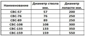
The most common pile cross-section sizes:
- 200x200 mm;
- 250x250 mm;
- 300x300 mm;
- 350x350 mm;
- 400x400 mm.
Products with large dimensions are used in individual projects associated with special construction conditions.
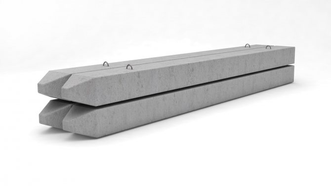
Reinforced concrete piles have a pointed end for easier entry into the soil
Rectangular piles are produced with a tip reinforced with reinforcement for better penetration into the soil, but more economical piles without a tip are also produced, the pressure created by pressure mechanisms is sufficient for their installation.
The scope of application of such products is limited to soils without impassable inclusions.
In low-rise residential construction, piles with a section of 300 by 300 mm and a length of up to 6 m are usually used.
They have sufficient load-bearing capacity, are easy to transport, and do not require overly complex and powerful equipment for transportation and movement on the construction site.
7-2
Crap. 4
Table I List of rods for one shortened frame
| Mani frame | Position | Sketch | Diameter, mm, class | £-30 | | Dlila | Quantity | |
| m | |||||||
| KU7-30 | / | Pos. / | I2AI | 6970 | 6970 | 4 | |
| 2 | 5B1 | — | 42720 | 1 | |||
| KU8-30 | ! | 1 | L '30 | 12AI | 7970 | 7970 | 4 |
| 2 | — | SBI | 47720 | 1 | |||
| KU9-30 | 1 | 12A1I | 8970 | 8970 | 4 | ||
| 2 | Pos. 2 | 5BI | 62720 | 1 | |||
| KUYU-30 | / | 12A1P | 9970 | 9970 | 4 | ||
| 2 | •> •> | G | N\I\I\N\N\ | 5B1 | 57720 | 1 | |
| KUN-30 | 1 | 14LSH | 10970 | 10970 | 4 | ||
| 2 | 5BI | 1— | 62720 | 1 | |||
| KU12-30 | t | 14AH | 11970 | 11970 | 4 | ||
| 2 | 5BI | 67720 | 1 | ||||
| KU8-35 | 1 | I2AII | 7970 | 7970 | 4 | ||
| 2 | 5BI | 57210 | 1 | ||||
| KU9—35 | / | 12LP | 8970 | 8970 | 4 | ||
| 2 | 5BI | t— | 63190 | 1 | |||
| KU10—35 | ! | Pos. 1 | 12AP1 | 9970 | 9970 | 4 | |
| 2 | 5BI | 69180 | 1 | ||||
| KU 11-35 | 1 | J | L '30 | I4AIII | 10970 | 10970 | 4 |
| 2 | 1 | 5BI | 75140 | 1 | |||
| KU12-35 | 1 | I4A1I1 | 11970 | 11970 | 4 | ||
| 2 | 5BI | $1140 | 1 | ||||
| KU13-35 | 1 | Pos. 2 fVWJVVV | 16A111 | 12970 | 12970 | 4 | |
| 2 | 5BI | — | 87130 | 1 | |||
| KU14-35 | 1 | !6А1П | 1*3970 | 13970 | 4 | ||
| 2 | AND | 5B1 | G- | 93110 | 1 | ||
| KU 15-35 | 1 | I8AI1I | 14970 | 14970 | 4 | ||
| 2 | 5B1 | — | 99090 | 1 | |||
| KU16-35 | / | 20AIII | 15970 | 15970 | 4 | ||
| 2 | 5BI | 105080 | J | ||||
| KU13-40 | 1 | I6AI11 | 12970 | 12970 | 4 | ||
| A | Pos. / | 5B1 | 101590 | 1 | |||
| 2 | 4 | ||||||
| 1 | i | I8AIII | 13970 | 13970 | |||
| KU14-40 | 1 | 1’30 | 1 | ||||
| 2 | 4- | — . Ch** | 5BI | 108560 | |||
| J | 18L111 | 14970 | 4 | ||||
| KU15—40 | M9TO | 1 | |||||
| 2 | Pos. 2 | 5BI | |||||
| 115530 | |||||||
| 1 | 20AI11 | 15970 | 4 | ||||
| JV L | wwwvw | 15970 | 1 | ||||
| KU16-40 | 2 | L | 5BI | 12250 |
List of rods for the spiral head and the frame of the tip
| PSPSRSCNOG section of the Sahak. cm | Brand name | Position |
| 20 | SG20 | 1 |
| 25 | SG25 | / |
| 30 | sgzo | / |
| 20 | KO20 | 2 |
| 7 | ||
| 25 | KO25 | 3 8 |
| 30 | K 030 | 4 |
| 9 | ||
| 36 | KO35 | 5 |
| to | ||
| 40 | KOYU | 6 |
| And |
Sketch or section
table 2
| Lia-megr, mm. Class | Lago-tonka length t | 4 | «1 | V" | 1. | Quantity | |
| We | |||||||
| 5BI | 3100 | 135 | — | — | — | — | 1 |
| 5BJ | 4650 | 185 | — | — | — | — | 1 |
| 5B1 | 5900 | 235 | — | — | — | — | 1 |
| YA1 | 540 | — | 160 | — | 95 | 245 | 2 |
| 5BI | 2000 | — | — | 115 | — | — | 1 |
| 10A1 | 720 | — | 230 | — | ISO | 330 | 2 |
| 5B1 | 3000 | — | — | 165 | — | — | 1 |
| I0A1 | 780 | — | 290 | — | 190 | 340 | 2 |
| 5B1 | 3100 | — | — | 205 | — | — | 1 |
| I0A1 | 840 | — | 330 | — | 220 | 370 | 2 |
| 5BI | 4400 | — | — | 235 | — | — | I |
| I0AI | 990 | — | 420 | — | 280 | 430 | 2 |
| 5B1 | 5800 | — | — | 295 | — | — | 1 |
Table I
17
Sampling of steel for one shortened frame
| Jurkas brand | Reinforcing steel | Total weight, kg | |||
| according to GOST 6781-75 | according to GOST 6727-53, class B-1 | ||||
| Diameter, mm class | Weight, kg | Diameter, mm | Weight, kg | ||
| KU7—30 | 12AI | 24.8 | 6,6 | 31,4 | |
| KU8-30 | 28.3 | 7,4 | 35.7 | ||
| KU9-30 | 12AI1 | 31,9 | 5 | 8.1 | 40.0 |
| KU 10-30 | I2A11I | 35,4 | 8.9 | 44.3 | |
| KUP-» | 53.0 | 9.7 | 62.7 | ||
| KU 12-30 | MASH | 57,8 | 10,4 | 68,2 | |
| KU8-35 | I2AII | 28,3 | 8.8 | 37.1 | |
| KU9-35 | 31,9 | 9.7 | 41.6 | ||
| KUYU-35 | 12A11I | 35,4 | 10,7 | 46,1 | |
| KUN-35 | 14A111 | 53.0 | 11.6 | 64,6 | |
| KU 12-35 | 57,8 | 5 | 12,5 | 70,3 | |
| KU13-35 | I6AIII | 81.9 | 13.4 | 95,3 | |
| KU14—35 | 88,2 | 14,3 | 102.5 | ||
| KU 15-35 | I8AIII | 119,6 | 15.3 | 134,9 | |
| KU 16—35 | 20AIII | 157,5 | 16,2 | 173,7 | |
| KU 13—40 | 16АШ | 81,9 | 15,7 | 97,6 | |
| KUN-40 | 18A1P | 111,6 | 16,7 | 128,3 | |
| KUYU-40 | 119,6 | 5 | 17,8 | 137.4 | |
| KU 16-40 | 20A1P | 157,5 | 18,9 | 176,4 |
Table 4
Sampling of steel for one element (helix of the head and frame of the tip)
| Item brand | Reinforcing steel, kg | Total weight, kg | |
| GOST 5781-75, class AJ, diameter 10 mm | GOST 6727-53. class B-1, diameter 5 mm | ||
| SG20 | 0,5 | 0.5 | |
| SG25 | — | 0,7 | 0.7 |
| SGZO | 0.9 | 0.9 | |
| whom | 0.7 | 0,3 | 1.0 |
| KO25 | 0.9 | 0,5 | 1.4 |
| KOZO | 1.0 | 0,5 | 1.5 |
| KO35 | 1.0 | 0.7 | 1.7 |
| KO4O | 1.2 | 0,9 | 2.1 |
3 Zai. KM
Hollow round piles
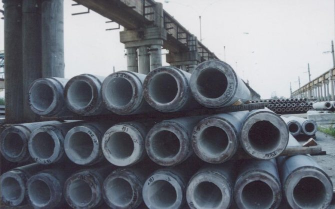
The use of round reinforced concrete piles is more relevant to industrial, hydraulic and energy construction. Unlike rectangular elements, round ones are made by centrifugation, which significantly increases the density and strength of the concrete mixture. Thanks to better manufacturability and thin-walled construction, round hollow piles are lighter than their solid counterparts; they require less concrete and less reinforcement.
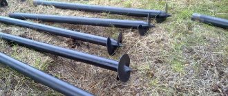
They are available with a pointed and open end, with a diameter from 300 mm to more than a meter cross-section, the length of the pile starts from 6 m. The head of a round pile can be equipped with a clip for building up sections. The ring knife on the lower edge of the element increases the specific pressure on the ground, facilitating effective immersion.
It is worth mentioning such a feature of the operation of hollow piles as the formation of a soil core inside the cavity during immersion. Having a high density due to mechanical loads, it gives the pile additional load-bearing capacity.
However, this effect is characteristic only of dense compressible soils; it does not occur on weak, loose and water-saturated foundations.
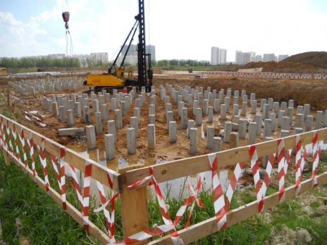
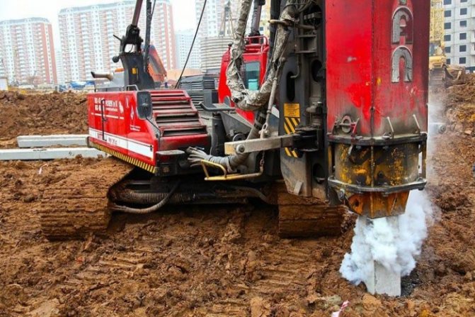
Submersion technology
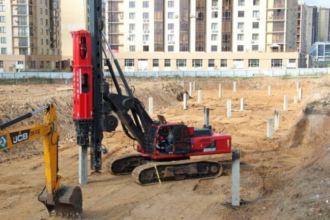
Equipment and piles are delivered to the work site and stored around the site. To optimize the work process, the supports are placed on the ground within the reach of the pile driver. While the support is positioned horizontally, marks are applied to it with bright paint. They are placed a meter apart so that the operator controls the immersion of the support into the ground when driving. A winch with hooks is lowered from the piledriver mast, which is fixed to the hinges of the support.
The pile is placed vertically above the installation point and centered. The upper end is located under the hammer. The frame is lowered along the pile driver and fixes the support, preventing it from moving when driven in. The support is placed between the mast guides. The sharp tip of the pile is placed above the installation point. The deviation of the tip from the point does not exceed 1 cm. Before driving, the verticality of the support and the coincidence of the axis with the hammer are checked.
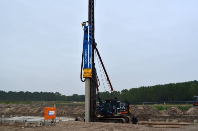
The task of the first blows is to direct and fix the support in the ground. They are applied once. The hammer rises 40 cm above the end of the pile. The intensity of impacts on the support increases when a meter of soil is passed. After 1.5 meters the amplitude is maximized. The position of the pile in the vertical plane is periodically verified. If a deviation of 1% is noticed, then ties or supports are used. They must return the axis of support to the point. In case of large or repeated deviations, the pile is removed and driven in again.
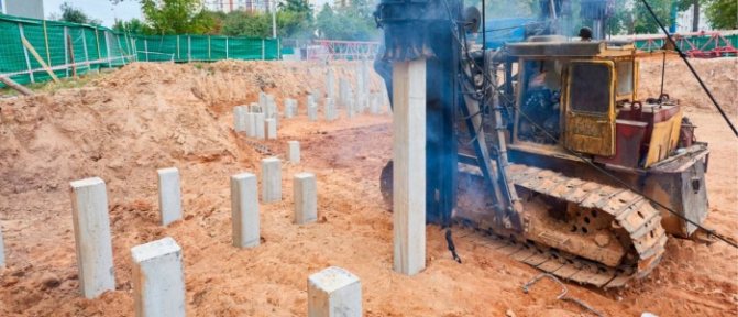
The support is immersed to the bottom mark or until the design failure. The last indicator is calculated before the start of work or in a practical way. Failure is a depth mark at which further immersion of the support becomes difficult or impossible. The indicator depends on the type of pile and soil. Geological surveys with preliminary drilling indicate the composition of the soil and the location of the layers.
A true support failure is checked after two months. Time is necessary for the pile to “rest”. If, after repeated driving, the pile does not move within the limits specified in the project, then the work is considered completed. False failure is the difficulty of moving a support in the ground due to its compaction. When friction against the walls occurs, the soil compresses, suspending the pile. In this case, the support for the foundation may not be sufficient.

Piles are driven according to three schemes:
- private;
- spiral;
- sectional.
Private is also called field. The arrangement of the supports corresponds to the name - in rows. The number of rows and the number of piles in each depends on the project. The first support placement scheme is used on sandy soils that are not compacted under dynamic loads.
The second scheme for placing supports is used on clay and loamy soils. Driving piles occurs in direct or reverse order. Straight - the drilling machine moves from the edge to the center. Reverse - from the center to the edges. The first is suitable for loams with normal density, the second - for dense clay soils.
When sectional driving of supports into the ground, a pile field is formed, similar to the first option. The difference lies in the way the supports are immersed. After the first two rows are completed, one is skipped. This happens until the end of the field. Once the area is covered with supports, the drilling machine returns and fills in the gaps. This method of installing piles on high-density soils is used. The process of installing supports using driving machines is shown in the video below.