The foundation is the basis of any permanent structure and can be made of various materials depending on the condition of the soil, technical features of the building, design loads and other things that influence the choice of foundation design and technology for its construction.
If for residential individual houses built on hard, durable soils, strip foundations made of monolithic or prefabricated reinforced concrete are predominantly used, then on heaving and moisture-intensive soils, strip foundations are often installed using pillars and beams that form a single grillage structure.
Preparatory work
Before the development of soil in pits and installation of foundations begins, the following work must be completed:
— access roads were built;
— vegetable soil was removed and placed in a dump;
— the site is planned;
— surface water drainage has been arranged;
— alignment work has been carried out and the axes of the foundations have been marked;
— an electrical lighting network for the site was installed;
— equipment, devices and means for safe work have been prepared;
— machines and mechanisms were delivered and placed on the site;
— brigades are staffed;
— living quarters for workers and engineers have been prepared;
— building materials and structures were delivered to the workplace;
— work on waterproofing the foundations has been completed;
— work orders were prepared and issued to workers.
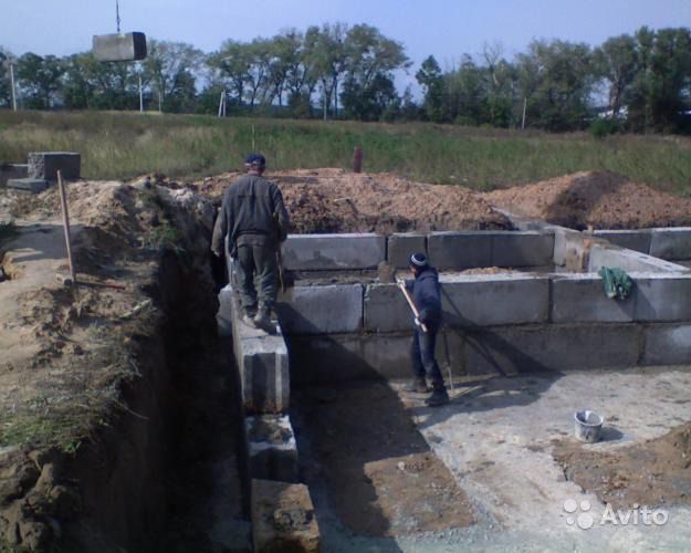
How to lay FBS blocks, laying foundation blocks
The abbreviation FBS refers to foundation and wall blocks. Some builders call them basement walls. The main purpose of the products is the construction of all kinds of structures that can be used from -70° below zero to +50° hot. Installation of blocks is possible on any type of soil in any climatic region of the country.
Sole preparation
The installation of foundation blocks begins after the axes of the future foundation are laid out. This procedure starts with the removal of the corners of the foundation and all its axes to the area. For this purpose, cast-off “benches” and manual measurement of all parameters are used.
The installation of FBS is carried out on a well-compacted bed of sand screenings, unless the design documentation prescribes the installation of a different type of base. The soil in the base is leveled strictly according to design guidelines.
As for areas with sandy soil, you don’t need to make a cushion on them - it’s enough to compact the soil itself well. If installation will be carried out on a sand substrate, its thickness should be more than 5 cm, the optimal value is 10 cm.
The sandy base for the FBS blocks should protrude 20-30 cm on each side, this will prevent fragments from hanging from the support. To increase the load-bearing capacity of the base of the future building and somewhat compensate for the weight of the FBS blocks, special pillows - FL - are laid out as the base. These building elements perform a single function - they expand the base of the support.
The installation itself
Manual installation of foundation blocks is practically impossible, so lifting equipment is used for the work. This is primarily due to the fact that the weight of the fragments of the future foundation is rather large.
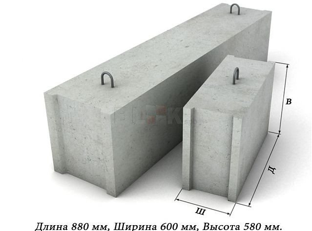
The range of FBS sizes is extremely wide
The start of slinging should be preceded by a thorough inspection of the position of the crane - the tracks and wheels of the machine should be located outside the boundaries of the possible collapse prism.
Installation is carried out in stages and involves following a certain sequence of actions:
1) laying corner lighthouse blocks, as well as marking wall intersection areas with supports;
2) tension along the edge of the corner beacons of the berth, alignment of intermediate blocks along it;
3) when one row is completed, the berth rises higher and still acts as a guide;
4) the location of the blocks according to the plan is controlled by the marks marked on the upper faces of the foundation, using a plumb line or theodolite;
5) if the block is laid unevenly, it is lifted by a crane, the base is leveled and the fragment is lowered back. Pulling blocks and using the manual method of forming the base is unwise;
6) FBS installation is carried out “staggered” according to the type of brickwork - the blocks are fixed on cement mortar, the number of rows is from 3 to 5.
Wall blocks are laid using mortar, vertical seams are tied to a depth of up to 40 cm (depending on the type of soil: subsidence, highly compressible, swelling, etc.).
Some features of the process
The weight of the structure does not allow the widespread use of the manual method of forming the foundation, but in private house-building there are cases of home-made production of smaller blocks and the construction of supports for the house on their basis. The manual method of moving factory FBS blocks, the weight of which varies in the range of 0.31-1.96 tons, is physically impossible.
Before laying on the base, the wall blocks are cleaned of dirt, moistened with water from a hose and placed on a 20 mm thick cement mortar. During installation, a solution is poured into the vertical gaps, which must be bayoneted to get rid of air voids.
If the length of all the blocks laid in one line is not enough for the side of the building, builders make gaps between the building fragments. Additional blocks or monolithic inserts called fillings are placed in these gaps. In addition, gaps are often left between FBS elements for laying utility lines.
When the foundation blocks have been completely installed, excess mortar is cut off and deficiencies are filled in again.
Important: the thickness of the foundation blocks does not have to be wider than the walls of the main building, but the maximum overhang of the wall on one side cannot exceed 13 cm.
The dimensions and weight of foundation wall blocks are given in the table
| Building block brand | Weight in tons | Dimensions in mm |
| FBS 24-3-6t | 0,975 | 2380 x 300 x 580 |
| FBS 24-5-6t | 1,63 | 2380 x 500 x 580 |
| FBS 12-3-6t | 0,49 | 1180 x 300 x 580 |
| FBS 12-5-6t | 0,814 | 1180 x 500 x 580 |
| FBS 12-4-3t | 0,31 | 1180 x 400 x 280 |
| FBS 9-5-6t | 0,51 | 880 x 500 x 580 |
| FBS 12-6-3t | 0,46 | 1180 x 600 x 290 |
| FBS 12-5-3t | 0,38 | 1180 x 500 x 280 |
rfund.ru
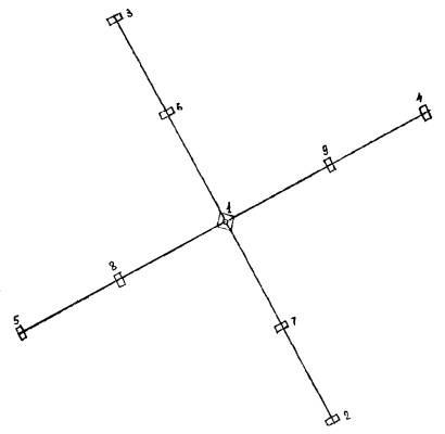
Sequence of work on foundation installation (see Fig. 2):
Note. The sequence of backfilling pits corresponds to the sequence of installation of foundations.
Rice. 2. Sequence of installation of foundations:
1 - central foundation of CF-1; 2, 3, 4, 5 — anchor foundations AF-18 of the second tier of guys; 6, 7, 8, 9 — anchor foundations AF-8 of the first tier of guys
— excavation of soil in a pit for the central foundation using an excavator;
— collecting soil and cleaning the bottom of the pit to the design mark using shovels;
— arrangement of crushed stone bedding under the central foundation;
— verification of the design mark for laying reinforced concrete foundation blocks;
— installation of a prefabricated central reinforced concrete foundation;
— installation of embedded parts;
— backfilling of the foundation sinuses with layer-by-layer compaction of the soil;
— embankment device;
— excavation of soil with an excavator in the pits of anchor foundations of the second and first tiers successively;
— manual collection of soil to the design mark;
— installation of anchor foundations of the second tier;
— backfilling of the sinuses of the anchor foundations of the second tier with layer-by-layer compaction of the soil;
- embankment of foundations.
The construction of foundations is carried out in two shifts.
To avoid filling the pits with water, the installation of foundations should be carried out after the completion of soil excavation and verification of the design marks for the depth of the pits.
Areas for storing foundation blocks must be planned. Foundation blocks are stored on wooden pads of square or rectangular cross-section. The use of round pads is not permitted.
#G0TYPICAL TECHNOLOGICAL CARD (TTK)
INSTALLATION OF FOUNDATION BLOCKS
1 AREA OF USE
A typical technological map has been developed for the installation of foundation blocks.
Prefabricated strip foundations
consist of prefabricated foundation pads, reinforced according to calculations, above which wall blocks are installed. Reinforced concrete foundation slabs and concrete wall blocks are unified; the nomenclature provides for their division into four groups, each of which differs in the perceived load. To increase the rigidity of the structure, to level out settlements during construction on soft soils and as anti-seismic measures, prefabricated foundations are reinforced with reinforced seams or reinforced concrete belts placed on top of foundation pads or the last row of wall foundation blocks along the entire perimeter of the building at the same level. For sandy soils, foundation blocks are laid directly on a leveled base, for other soils - on a sand cushion 10 cm thick. Bulk or loosened soil cannot be left under the base of the foundations; it must be removed and sand or crushed stone filled in instead. Depressions in the soil foundation more than 10 cm high are filled with monolithic concrete. The width and length of the sand base are made 20...30 cm larger than the dimensions of the foundation so that the blocks do not hang from the sand cushion. Foundation blocks are laid according to their layout in accordance with the design (Fig. 1) to provide breaks for laying water supply, sewerage and other inputs.
Fig.1. Installation of prefabricated strip foundations: 1 - foundation pad; 2 —
wall block;
3 -
sand preparation;
4 -
reinforcing belt;
5 - bed of mortar; 6 -
sealing the joint with monolithic concrete; 7 — slinging the block
Installation begins with the installation of lighthouse blocks in the corners and at the intersections of walls. The foundation block is transported by crane to the installation site, pointed and lowered onto the base; minor deviations from the design position are eliminated by moving the block with a mounting crowbar while the slings are tensioned. In this case, the surface of the base should not be disturbed. The slings are removed after the block takes the correct position in plan and height. During the installation process, the gaps between the strip foundation blocks and the side cavities are filled with sand or sandy soil and compacted. When installing foundations for columns, carefully control the position of the installed blocks relative to the main axes. Using levels, the position of the blocks in height is controlled; for glass-type blocks, the mark of the bottom of the glass is checked; for others, the upper plane of the block is checked. The installation of basement walls (wall blocks) begins after checking the position of the laid foundation blocks (pillows) and the waterproofing device. If there are no special instructions in the project, then a layer of mortar 2...3 cm thick is spread over the cleaned surface of the foundations as insulation; the solution simultaneously serves as a leveling layer. In accordance with the installation diagram, the position of the wall blocks of the first (bottom row) is marked on the foundations, noting the locations of the vertical seams. Installation begins with the installation of lighthouse blocks in corners and places where walls intersect at a distance of 20...30 m from each other. After installing the lighthouse blocks at the level of their top, a cord is pulled - a mooring, along which ordinary blocks are installed. Subsequent rows of blocks are mounted in the same sequence, marking the layout of the blocks on the underlying row. The first two rows of blocks are installed from laid foundation blocks, the subsequent ones - from inventory scaffolding. The brand of mortar on which the blocks should be mounted is indicated in the project. The installation crane can be placed on the edge of the pit, then within the boundaries of the excavation, all the foundation blocks are first installed, and then the basement wall blocks. If the crane is located in a pit, then the foundations and walls of the basement are installed in separate sections, based on the fact that the installation crane will not be able to re-enter the area where the blocks have already been laid
2. ORGANIZATION AND TECHNOLOGY OF WORK EXECUTION
Installation of prefabricated strip foundations
Performers
Installer IV category (M1) - 1; Installers of the III category (M2, M3) - 2; Truck crane operator of category V (M) - 1.
Sequence of operations
Before laying the blocks it is necessary to: - check the correct alignment of the building axes; — fully prepare the foundation in accordance with the project and technical specifications; — when working in winter conditions, protect the base from freezing (the blocks are laid on thawed soil); — prepare and place a complete set of blocks in the crane’s operating area; — clean the blocks from dirt and ice. Work should be carried out in full compliance with the safety and labor protection rules for workers. Installation of prefabricated strip foundations is carried out in the following order: - prepare the base and blocks; — mark the places where the blocks will be laid and place them; — fill the joint with concrete mixture and seal the horizontal seam.
Fig.2. Workplace organization 1
— place for storing blocks;
2
- platform for receiving the solution;
3
- truck crane; M, M1, M2, M3 - work stations for installers.
Checking, slinging the block and cleaning its lower plane (M3, M, sling, scraper, sledgehammer; Fig. 3, 4).
The M3 installer, having checked the markings, geometric dimensions of the foundation blocks and the reliability of the mounting hinges, rafters the block.

At a signal from the M3 installer, the M crane driver lifts the block to a height of 50-70 cm. Having made sure that the sling is secure and having cleared the lower plane of the block from dirt and ice, the M3 installer gives a signal to further lift and move the block to the trench.

Delivery of the block to the place of installation (M3, M, sling).
The operator of crane M smoothly lifts the block and delivers it to the installation site.
The M3 installer accompanies the block to the edge of the pit. Marking the place for laying the block (M1, M2, tape measures, shovels, wedges; Fig. 5).
Installers M1 and M2 mark the location of the block and, if necessary, clean the supporting surface.
Fig.5.
Installer M2 spreads the mortar over the supporting surface with a shovel, and installer M1 levels it with a layer 20-30 mm thick. The strips of mortar should be 30-40 mm away from the edges of the block. Receiving and placing the block in place (M1, M2, M, slings, crowbars; Fig. 6).
Installers M1 and M2 take the block at a height of approximately 30 cm above the previously laid ones and unfold it. At the command of the M2 installer, the driver smoothly lowers the block to a height of 10-15 cm from the supporting surface. The installers use crowbars to straighten the block along the marks and moorings, installing it in the design position; after which the driver lowers the block onto the supporting surface.
Aligning the block and unslinging it (M1, M2, M, sling, level, plumb line, crowbars; Fig. 7).
Installers M1 and M2 check the horizontality of the laid block with a level, and the verticality of the edges with a plumb line.
The position of the block relative to the previously laid ones is checked along the berth, and leveled using crowbars and wedges with a tensioned sling. Then the installers release the sling and make the final alignment of the laid block. Feed the sling to the next block (M).
The operator of crane M, at a signal from installer M2, smoothly lifts the sling and moves the boom to the place where the blocks are stored.
Sealing seams (M3, trowel, shovel, darning, mortar box; Fig. 8).
The M3 installer fills the vertical joint with a concrete mixture, and then, by darning, compacts the mortar in the horizontal joint.

Instructions for carrying out work
#M12291 871001100SNiP 3.03.01-87#S pp. 3.9, 3.11
Installation of foundation structures is permitted only after completing the entire complex of excavation work, laying out the axes and laying the foundation. Before installation begins, marks should be applied with indelible paint on the upper edges of foundation slabs and blocks and at their bases, fixing the position of the axes of the slabs and blocks. The supporting surfaces of slabs and blocks must be cleaned of contamination. The installation of basement wall blocks should be done, starting with the installation of lighthouse blocks in the corners of the building and at the intersection of the axes. Lighthouse blocks are installed by combining their axial marks with the marks of the alignment axes in two mutually perpendicular directions. The installation of ordinary blocks should begin after checking the position of the lighthouse blocks in plan and height. Row blocks should be installed with the bottom oriented along the edge of the blocks of the bottom row, and the top along the alignment axis. External wall blocks installed below ground level must be aligned along the inner side of the wall, and above - along the outer side. Vertical and horizontal seams must be filled with mortar and embroidered on both sides.
Performers:
worker performing installation work, senior in the unit;
worker performing installation work;
Workplace organization diagram (Fig. 9) and the order of work.
Fig.9. Scheme of workplace organization during installation of strip foundation blocks: MS, M
— working positions of installers;
1
- mounted foundation blocks,
2
- mounting crowbar,
3 -
mortar shovel,
4 -
mounted block, 5 - box with hand tools,
6
- wooden strip.
The rigger prepares the block for installation and delivers it. He slings the block, checks the correctness of the hook, cleans it of dirt and concrete deposits, and, making sure that the block is ready for installation, sends it to the installation site. The installers prepare the installation site for the block: using wooden stakes, previously driven to the design mark of the block’s base, as guides, they level the base with shovels. Then the installers take the block at a height of 200...300 mm from the base surface, orient it in the desired direction and allow the crane operator to lower it onto the prepared bed. The correct installation is verified using an axial wire stretched on a castoff (this wire fixes the edge line of the block). Using a plumb line, check whether the position of the mounted block corresponds to the design one. If there is deviation, the block is straightened using a mounting crowbar.
Permissible deviations, mm
Installers dismantle the unit if necessary. They sling the block, after lifting it, inspect the quality of the sling, clear the block of sand and soil, then allow the block to be moved to the storage area, where the installer receives it, places it on supports and removes the slings.
Preparing the block for installation (Fig. 10), worker performing rigging work
Fig. 10. Scheme for lifting a prefabricated foundation block: 1 —
wooden pads,
2 -
wooden spacers,
3 -
lifting block,
4 -
universal lifting device,
5 -
worker performing rigging work.
1. Signals the crane operator to apply the universal lifting device 4
to the block storage area.
2. Places the hooks of the device one by one behind the mounting loops of the block 3.
3. Signals the crane operator to tighten the sling.
4. Moves away from the block to a safe area at a distance of 4000...5000 mm.
5. Gives a signal to the crane operator to lift the block to a height of 200... 300 mm.
6. Inspects the quality of the sling. If the block is not properly lashed, it is lowered at the command of the rigging worker, who slings it again and allows it to be raised to the same height.
7. Inspects the surface of the block and cleans it of concrete and dirt.
8. Gives a signal to supply the element to the installation site.
Preparing the installation site for the block (Fig. 11), performers
Fig. 11. Sand base preparation scheme: 1
- prepared base,
2 -
mounted block,
3 -
mortar shovel,
4
- worker performing installation work,
5
1. The worker performing installation work, the senior in the link and the worker performing installation work check whether there are stakes marking the base mark. 2. The worker performing installation work, the senior in the link and the worker performing installation work use shovels to level the base 1
under the block, focusing on the level of pre-hammered wooden stakes.
3
as needed . 4. The worker performing installation work, the senior in the team, periodically checks the horizontalness of the base: installs a strip on the top of the stakes and measures the gap between the strip and the sand level with a metal ruler (the gap should not exceed 5 mm). 5. The worker performing installation work, the senior in the link and the worker performing installation work lay out tools, fixtures and equipment according to the workplace diagram. 6. The worker performing installation work, the senior in the link and the worker performing installation work tension the axial wire.
Installation of the block
(Fig. 12), performers
: worker performing installation work, senior in the link and worker performing installation work
Fig. 12. Installation diagram of prefabricated foundation block: 1
- sand base,
2 -
mounted block,
3 -
worker performing installation work,
4
- universal load-handling device,
5
- mounted block,
6
- worker performing installation work, senior in the link.
1. The worker performing installation work, the senior in the team, gives a signal to the crane operator to move the block 5
to the installation area.
2. The worker performing installation work, the senior in the link and the worker performing installation work accept block 5
at a height of 200... 300 mm from the base surface. 3. The worker performing installation work, the senior in the link and the worker performing installation work guide the block, focusing on the axial wire that fixes the edge line of the block. 4. The worker performing installation work, the senior in the link and the worker performing installation work hold the block at the moment of lowering.
Block alignment
(Fig. 13), performers
: worker performing installation work, senior in the link and worker performing installation work
Fig. 13. Alignment diagram of the installed block: 1
- mounted block,
2
- plumb line,
3 4 -
axial wire,
5 -
mounted block,
6 -
crowbar, 7
-
worker performing installation work.
1. The worker performing installation work, the senior in the link, attaches a plumb line 2 to
axial wire
4
and checks the position of the block.
If there are deviations from the design position, it gives a command to the worker performing installation work to move the block. 2. The worker performing installation work uses a crowbar 6
to move the block in the desired direction. 3. The worker performing the installation work, the senior in the team, re-checks the accuracy of the installation of the block.
Unslinging the block
(Fig. 14), performers
: worker performing installation work, senior in the link and worker performing installation work
Fig. 14. Scheme of bridging of the installed block: 1
- worker performing installation work, senior in the unit,
2
- worker performing installation work.
1. The worker performing installation work, the senior in the team, gives the command to the crane operator to loosen the slings. 2. The worker performing installation work, the senior in the link and the worker performing installation work remove the hooks from the mounting loops of the block. When preparing the foundation, it is important to practice the process of self-control. the worker performing installation work, the senior in the link, periodically applies a lath to the upper end of the driven stakes or to the marks marked on them. The bottom of the batten fixes the level of the sandy base, the quality of which is determined by the deviation from the horizontal. Since the rack is in a horizontal position, it is necessary to measure the gap between the lower edge of the rack and the base surface at several points. Students must identify these points by first marking them visually. If the gap between the bottom edge of the attached rail and the base exceeds 5 mm or there are more than three deviations per length of the rail exceeding 3 mm, then the base is unsuitable for installation of structures. The accumulation of a certain number of deviations leads to a decrease in the quality of work. If there are fewer inaccuracies than normal, then the work is considered satisfactory. This reveals the law of the transition of quantity into quality. Maximum deviations: - from the alignment of the wall blocks with the alignment guidelines with the marks of the alignment axes - no more than 12 mm; - from the vertical of the top of the planes of the wall blocks - 12 mm. The brand of solution must correspond to the design one. The mobility of the solution for making a bed should be 5-7 cm. The installation of wall blocks should be carried out in compliance with the dressing. It is not allowed: - the use of a solution whose setting process has already begun, as well as the restoration of its plasticity by adding water; — contamination of supporting surfaces.
3. REQUIREMENTS FOR THE QUALITY OF WORK COMPLETION
Composition of operations and means of control #G0Stages of work
| Controlled Operations | Control (method, volume) | Documentation | |
| Preparatory work | Check: — availability of a quality document; — quality of the surface and appearance of the blocks, accuracy of their geometric dimensions; — transfer of the main axes of the foundations to cast-off; — preparation of foundation blocks for installation, including cleaning of supporting surfaces from dirt and ice. | Visual Visual, measuring Measuring Visual, every element | Passports for slabs and blocks, general work log |
| Installation of foundation blocks | Monitor: - installation of foundation blocks, compliance of their position in plan and height with the requirements of the project; — the density of contact between the base of the foundation blocks and the surface of the base; — filling the joints with cement mortar according to the requirements of the project. | Measuring, each element Visual Same | General work log |
| Acceptance of completed work | Check: - deviation of the planes of the wall blocks from the vertical; — deviation of the axes of the foundation blocks relative to the alignment axes; — filling the seams between the blocks with mortar. | Measuring, each element Visual | Executive geodetic diagram, work acceptance certificate |
| Control and measuring instruments: level, tape measure, metal ruler, plumb line, rule | |||
| Operational control is carried out by: a foreman (foreman), a surveyor - during the execution of work. Acceptance control is carried out by: a quality service employee, a foreman (foreman), a representative of the customer’s technical supervision |
Control of the accuracy of the installation of prefabricated strip foundations
Before starting construction work, marks that define the axes must be marked on the foundation blocks. If there are marks on the products, it is necessary to clarify their position. If the geometric shape of the block is correct, the longitudinal and transverse axes are taken to be the lines connecting the two intersection points of the diagonals of the side walls (Fig. 15).
Fig. 15. Axes and marks of the block: 1 - longitudinal axis; 2 - transverse axis; 3 - metal plates; 4 - risks
Axes are designated on the faces as traces of the intersection of planes drawn through the transverse and longitudinal axes perpendicular to the top face. In this case, not all the marks shown in Fig. 15 are applied, but those that are needed to install the block. In the planned position, the blocks are installed along mechanical plummets if the plumb line method is used, or along a theodolite if the vertical plane method is used. To install and align the height of foundation blocks, it is necessary to have two additional benchmarks at the bottom of the pit with marks on them indicating the level of the foundation base. The sequence of control measurements during the installation of prefabricated strip foundations can be as follows: 1) Pour a leveling layer, for example from sand, about 10 cm thick and 20 cm wide than the size of the pillow (Fig. 16). 2) Mark with pins or stakes the position of the corner and lighthouse blocks at the bottom of the pit. 3) Install frames or boards with marks of the axes of the blocks on the outside of the studs or stakes on a sand cushion and check their planned position. 4) Determine the height position of the frames or boards using a level and set them to the design mark. 5) Compact and level the sand cushion to the level of the frame or boards. 6) Place the blocks on the prepared base so that their main marks coincide with the marks of the frames or boards. 7) Check the position of the corner and beacon blocks using a level (in this case, the reading on the staff on the block should be less than the reading on the staff at the reference point by the thickness of the block). Control planned measurements of the sides and diagonals are made in sections limited by corner and lighthouse blocks and compare them with the design dimensions; 9) Pull a mooring at the level of the upper outer edge of the corner and lighthouse blocks or between the lighthouse blocks and control the installation of other blocks along it, filling the gap.
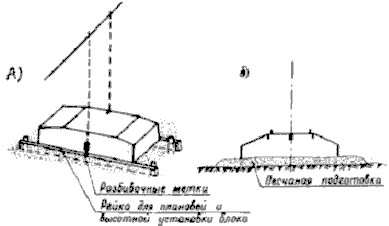
Fig. 16. Control of the accuracy of the pillow installation using alignment marks: a - general view; b - section
When laying the foundation, it is necessary to lay out holes for the passage of underground communications. The planned position of the inputs is determined by measurements from the main axes, and the height position - from benchmarks. The breakdown of the inputs must be carried out before assembling the blocks.
4. MATERIAL AND TECHNICAL RESOURCES
Tools, devices, inventory
Combined sling for lifting and installing blocks - 1; Container box with a capacity of 0.23 m for receiving and storing the solution - 8; Plumb line for aligning blocks - 1; Mortar shovel - 2; Scraper for cleaning the lower planes of blocks - 1; Darning for sealing horizontal seams - 1; Crowbar for straightening blocks - 2; Trowel for concrete and stone work - 2; Sledgehammer for bending mounting loops - 1; Construction level - 1; Tape measure for marking places for laying blocks - 2. Laying one block 238 cm long requires 12 liters of concrete mixture and 49 liters of solution.
5. ENVIRONMENTAL AND SAFETY RULES
INSTRUCTIONS
on occupational health and safety for the installer (installation of reinforced concrete structures)
I. General rules
1. Allowed for the installation of reinforced concrete structures are workers who are at least 18 years of age, who have completed training according to a standard program, have been verified by the administration in their knowledge of these instructions, and who have written permission to carry out work (permit).
2. It is allowed to work only where the foreman or foreman is assigned. 3. Do not start work without receiving an introductory safety briefing and instructions on safe work practices at a given workplace.
4. On the construction site, the following rules must be followed: a) be attentive to the signals given by crane operators and drivers of moving vehicles and comply with them; b) do not be under a raised load; c) pass only in places designated for passage and indicated by signs; d) do not cross the path in front of moving vehicles; e) do not go beyond the fences of dangerous areas; f) bypass places where work is carried out at height at a safe distance, since objects may accidentally fall from a height; g) do not look at the electric welding flame, as this may cause eye disease; h) do not touch electrical equipment and electrical equipment. wires (especially bare or broken), do not remove fences and protective covers from live parts of the equipment; i) do not fix electrical faults yourself. equipment, call an electrician; j) do not operate machinery without undergoing special training and obtaining permission; k) in the event of an accident, immediately seek medical help and at the same time inform the foreman (foreman) about the accident; l) if you notice a violation of the instructions by other workers or a danger to others, do not remain indifferent, but warn the worker and foreman about the need to comply with the requirements to ensure work safety.
II. Responsibilities before starting work
5. Check the serviceability and suitability of all rigging devices, make sure that the installation crane is securely installed. 6. Prepare the installation tool for work. 7. Inspect fences, scaffolding, scaffolding and make sure they are in good condition and stable. 8. If you find malfunctions or defects in the rigging devices (breakage of cable strands, bending, breakage of traverses, containers), installation tools or fences, report this to the foreman and begin work only with the permission of the foreman. 9. Check that the workplace lighting is sufficient. 10. To avoid electric shock, carefully inspect nearby electrical wiring and, if exposed, uninsulated wires are found, report this to the technician. 11. When work is carried out simultaneously at different levels along the same vertical, a continuous flooring or continuous mesh must be made at each level to protect those working below from any objects or tools falling from above.
III. Requirements while working
A. When installing foundations and basement walls
12. The workplace must be cleared of foreign objects and planned. 13. Do not allow unauthorized persons into the installation work area. 14. Place prefabricated blocks and foundation pads 2 meters from the edge of the pit in stacks with spacers for connecting slings without turning the blocks. 15. If cracks or “peaks” are detected that threaten the collapse of a pit dug with slopes, stop work and report the danger to the foreman. 16. Clean blocks and foundation pads from ice, snow and dirt. Lifting blocks and pillows covered with soil or snow, as well as frozen to the ground, is prohibited. 17. Installation of the upper rows above 1.1 m should be carried out only from inventory scaffolds or from portable platforms. 18. When lifting structures, the alarm system must be organized in such a way that all signals to the crane operator, as well as to workers working on guy ropes, are given by only one person supervising the lifting and installation of structures (usually a foreman and, in especially critical cases, a foreman or foreman) . In all cases, the crane operator must be notified whose instructions he must follow. When installers are working outside the crane operator’s field of vision, reliable communication must be ensured between the crane operator and the installer’s workstations. 19. Areas hazardous to human traffic during installation must be fenced off and equipped with visible warning signals. It is prohibited for people to stay on the floors below the one on which construction and installation work is being carried out (in one area), as well as in the area where elements and structures are moved by cranes. 20. Sling products only by the mounting loops using slings equipped with hooks or carabiners. 21. Slinging of lifted elements should only be done with flexible steel slings or cables with a tag. The slings should be easy to put on and remove from the hook of the lifting mechanism, and also be easily released from the structures or elements being lifted. Slings must not have knots, loops or twists. When lifting, wooden spacers should be placed under the sharp edges of the structure to prevent chafing of the cable. Lifting is carried out using all existing mounting loops. 22. Slinging of reinforced concrete elements is carried out according to the developed schemes. 23. It is prohibited to be under the lowered product or allow it to be carried above the workplace. 24. Do not tighten the products before lifting or lowering. 25. When lifting the product, move it in a horizontal position when the product is elevated above other objects by at least 0.5 m. 27. Lower the presented product above the design position by no more than 30 cm and from this position guide and install the product in the design position . 28. After installing the product, loosen the cables and make sure again that it is installed correctly in the designed position. 29. Do not leave raised products hanging. 30. Do not place installed products on scaffolding. 31. Do not accept the product by hand for installation if it is raised above the installation site by more than 30 cm. 32. It is prohibited to lift or move installed products after unhooking the slings.
B. When installing prefabricated reinforced concrete structures
33. Installation of structures of each subsequent floor is allowed only after completion of the installation of the ceiling of the previous floor, as well as all work on fastening, welding and embedding of units. The openings and openings left in the ceilings should be fenced off or covered with decking. 34. Do not exceed the maximum lifting capacity of the crane at a given boom radius and do not exceed the maximum lifting capacity of rigging devices (slings, etc.). 35. Lift parts that have a weight close to the maximum weight in two steps. First, lift the part to a height of 20-30 cm and in this position check the suspension and stability of the crane, and then lift the part to its full height. 36. Do not allow the crane to pull loads by slanting the ropes or turning the boom. 37. Moving people with a crane is prohibited. 38. Lifting small piece goods (bricks, etc.), as well as bulk cargo, should be carried out in special containers that exclude the possibility of the cargo falling out of the container. 39. When installing partitions, firmly secure the traverse and prevent it from unhooking spontaneously. Closely monitor the load while lifting and moving it. 40. When installing blocks of flight stairs that do not have inventory fences, install temporary fences and only after that allow passage along the stairs. 41. When installing block jumpers, it is prohibited to stand on the wall and the mounted block and on the inventory scaffolding. 42. When installing floor slabs, staircases, etc., slinging should be done using all loops and the element being laid should not be allowed to warp. 43. Unslinging of mounted elements (slabs, balconies, cornices) should be carried out after installing them in the design position and welding the embedded hinges of the mounted element with the anchor. 44. Installation of large-panel partitions should be carried out from mobile stepladder scaffolds. 45. In case of strong wind (more than 6 points), ice, heavy snowfall, rain and fog, installation work at height must be stopped. 46. Slinging of long elements should be done with at least two slings and during installation it is necessary to control the elements from a distance with rope braces attached to both ends of the mounted element. 47. Welding and embedding of units of installed reinforced concrete structures must be carried out from ceilings fenced at the workplace, mobile scaffolds with fenced platforms at the top or suspended cradles. The welder must have a bag to collect cinders. 48. Reinforced concrete columns and frame racks must be equipped with installation ladders or hanging cradles for subsequent installation work and releasing slings, as well as for fastening or welding assemblies and installing crossbars. 49. For the transition of installers from one structure to another, installation ladders, transition bridges and ladders should be used. Movement along the lower chord of a truss or beam is allowed only if there is a safety belt stretched along their rope to engage the carabiner. The rope must be stretched tightly; sagging or weakening is not allowed. 50. The assembly and lifting of structures with a length of more than 6 m and a weight of more than 3 tons, which require special care when moving and installing them, should be carried out under the direct supervision of a foreman or foreman. 51. To plant structures and install them in place, it is necessary to use special crowbars or guy wires, and people are not allowed to be under the installed elements. 52. Blocks and hoists that are used for the installation of structures must be arranged in such a way that spontaneous falling of the cable or chain from the pulley, as well as their jamming between the block and the cage, is excluded. 53. Manual lifting winches must be equipped with an automatically operating brake or safety handles. During lifting, it is necessary to ensure consistent and correct winding of the cable onto the drum, avoiding winding above the side cheeks. 54. When working at height on riveting and welding without scaffolding, it is necessary to be tied to structures. 55. Disconnect the raised structure from the lifting hook or braces only after installing the structure on a sufficient number of bolts according to the work plan. 56. Install bolts using assembly wrenches of appropriate sizes. It is prohibited to place a gasket between the jaws of the key and the nut, and to use keys with broken lips. 57. Unslinging of installed elements is allowed only after strong and reliable fastening: a) columns - with anchor bolts or jigs and guys; b) trusses - with braces followed by connection with purlins and connections with previously installed and secured trusses; c) crane beams and rafter trusses - with bolts in an amount of at least 50 percent. design quantity; d) elements that have a welded attachment according to the design - with temporary mounting bolts with complete filling of all bolt holes.
IV. Requirements after work
58. Clean the workplace. 59. Put all the tools in the storeroom. 60. Report all noticed deficiencies to the foreman or foreman.
Electronic document text
prepared by Kodeks JSC and verified against
materials provided by A.A. Demyanov
Excavation
The excavation of the soil with the EO-4321 excavator is carried out first under the central foundation of the mast, and then sequentially under the anchor foundations of the second and first tiers of guys.
The excavation of the central foundation pit (see Fig. 3 and 4) is carried out by one excavator excavation with a dump of soil on two opposite sides, parallel to the axis of the excavation. The steepness of the pit slopes is determined depending on local conditions and the type of soil, determined according to the table. 4 SNiP III -A.11-70.
Excavation of soil for the anchor foundations of the second and first tiers is carried out by an excavator in one excavation with a dump of soil on three sides of the pit (see Fig. 5, 6 and 7).
What is a prefabricated strip foundation
A prefabricated strip foundation is a strip assembled from individual elements.
It has the same external contours and parameters as a monolithic concrete casting, but the construction technology complies with the rules for installing the elements used .
The prefabricated tape is installed according to the same principle, under all external and internal load-bearing walls of the house, providing a reliable supporting structure and taking on the load from the weight of the building.
The following elements are used for the construction of prefabricated belts:
- Brick . This option is practically not used in today's construction. The service life of such bases is only 30-50 years, which is too short compared to tapes made from other materials, so this option has become obsolete and is extremely rare.
- Cinder block . The properties of the material are not much superior to brick, but it becomes possible to significantly speed up construction due to the larger size of the blocks. It is not recommended to build such a foundation for residential buildings; the best option is buildings for household purposes.
- Foundation blocks (FBS). These are specialized foundation elements, which are large blocks. They are made from reinforced concrete that has undergone appropriate processing and are characterized by high strength and briquette density. The service life of FBS tape is on average 50-75 years, although longer operation is possible.
The choice of material is determined by the size and purpose of the building.
IMPORTANT!
To work with FBS, you will need lifting equipment, since the size of the blocks will not allow them to be laid manually. This is a drawback, but the other working qualities of the FBS fully compensate for it.