Processes occurring in the soil when piles operate under load
The vertical load carried by a friction pile
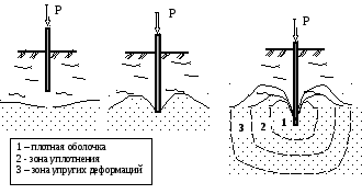
is transmitted to the ground through its side surface and lower end. As a result, a stressed zone appears in the soil around the pile, having a complex curvilinear outline.
The diagram of vertical normal stresses sZ at the level of the lower end of the piles has a convex shape. It is generally accepted that stresses sZ a with the pile , depending on the friction forces of the soil along its lateral surface.
When piles are sparsely located in a bush, the stressed zones of the soil around them do not intersect and all piles work independently, like single ones. With a small distance between the piles (as experiments have shown, less than 6d , where d is the diameter of the pile), stresses are superimposed, as a result of which the pressure on the soil at the level of the lower ends of the piles increases. Simultaneously with the increase in pressure under the pile cluster, a significantly larger overall active soil compression zone is formed, compared to a single pile. Due to these two reasons, with the same load, the settlement of the bush pile when the piles work together will always significantly exceed the settlement of a single pile.
As for the bearing capacity of bush piles, on the one hand, additional soil compaction caused by driving adjacent piles leads to its increase, and on the other hand, settlement of the soil between the piles as a result of the joint work of piles leads to its decrease, since friction forces are reduced along the side surfaces of the piles. Experiments show that in clayey soils, as well as fine and silty sands, the bearing capacity of a pile in a bush, as a rule, decreases compared to the bearing capacity of a single pile, and in large and medium-sized sands it increases. The described consequences of the joint work of piles in bushes are usually called the bush effect.
Lecture No. 8. Calculation of the bearing capacity of piles under the action of vertical loads
Rack piles. Since the loss of bearing capacity of a stand pile can occur either as a result of the destruction of the soil under its lower end, or as a result of the destruction of the pile itself, its calculation for vertical load is carried out according to two conditions: according to the condition of the strength of the material of the pile shaft and according to the condition of the strength of the soil under the lower end piles. The load-bearing capacity of the pile in the project is taken to be a smaller value.
Based on the strength of the material, piles are calculated as centrally compressed rods, rigidly clamped in the ground in a section located from the base of the grillage at a distance l1 , determined by the formula
l – length of the pile section from the base of the high grillage to the ground level, m; ae – deformation coefficient, 1/m, determined according to Appendix 1 of SNiP 2.02.03-85.
Load-bearing capacity of the Fdm most widely used in railway construction. b. prismatic piles is calculated by the formula
where j is the buckling coefficient; gcb – operating conditions coefficient, depending on the cross-section and type of pile according to SNiP 2.02.03-85; Rb – design resistance of concrete to axial compression depending on its class according to SNiP 2.03.01-84*, kPa; A – cross-sectional area of the pile, m2; ga – coefficient of operating conditions of the reinforcement, taken equal to 1; Rs – calculated compressive resistance of longitudinal working reinforcement depending on its class according to SNiP 2.03.01-84*, kPa; Aa is the cross-sectional area of the reinforcement, m2.
Based on the strength of the soil under the lower end of the pile, the bearing capacity Fd of the rack pile is determined by the formula
where gc=1 is the coefficient of operating conditions of the pile in the ground; R – calculated soil resistance under the lower end of the pile, kPa; A – area of support of the pile-rack on the ground, m2.
The calculated soil resistance R for all types of driven piles is assumed to be 20 MPa. For cast-in-place piles, if they are supported on solid rock, R is determined by the formula
and for piles embedded in unweathered rock to a depth of at least 0.5 m, according to the formula
where Rc,n is the standard value of the ultimate strength of rocky soil for uniaxial compression of soil in a water-saturated state, kPa; gg=1.4 – ground reliability coefficient; ld – depth of embedding of the pile into rocky soil, m; df – outer diameter of the part of the pile embedded in rocky soil, m.
Hanging piles. The load-bearing capacity of vertically loaded hanging piles is calculated only based on the strength of the soil, since the strength of the pile material is obviously higher.
| | | next lecture ==> | |
| Processes occurring in the soil during the installation of piles | | | The load-bearing capacity of a friction pile Fd is determined by the formula |
Date added: 2013-12-13; ; Copyright infringement? ;
Your opinion is important to us! Was the published material useful? Yes | No
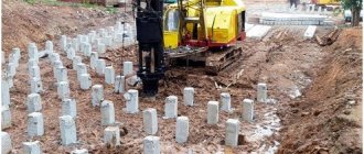
Drilled piles

Technology for constructing bored piles
Drilled piles are classified according to the method of construction.
- bored, concreted in wells drilled in silty-clayey soils above the groundwater level without securing the walls of the wells,
- bored, installed in wells drilled in any soil below the groundwater level - with the walls of the wells secured with clay solution or inventory casing pipes,
- drilling injection machines with a diameter of 150-250 mm, arranged by injecting fine-grained concrete mortar into drilled wells,
- drilled piles, constructed by lowering a reinforced concrete pile into a hole and filling the gap with a concrete mixture.
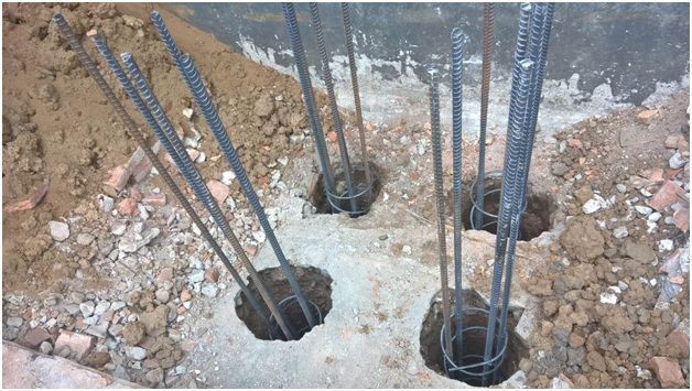
Types of bored piles differ in the method of construction and purpose. Actually, the main type is performed directly at the location by drilling a well, filling it with concrete mortar and reinforcing it with a frame prepared in advance for the entire or partial depth of the well from iron rods and wire.
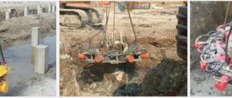
In difficult soil conditions, quicksand, sandy and soils at the level of underground aquifers, the installation of bored piles (BPS) is carried out under the protection of removable inventory casing pipes or under the protection of a clay (bentonite) solution. It is permissible to leave casing pipes in the ground if groundwater filtration exceeds 200 meters per day. Usually this becomes known from the results of engineering-geological surveys and cheaper retained pipes are used for the construction of the BPS.
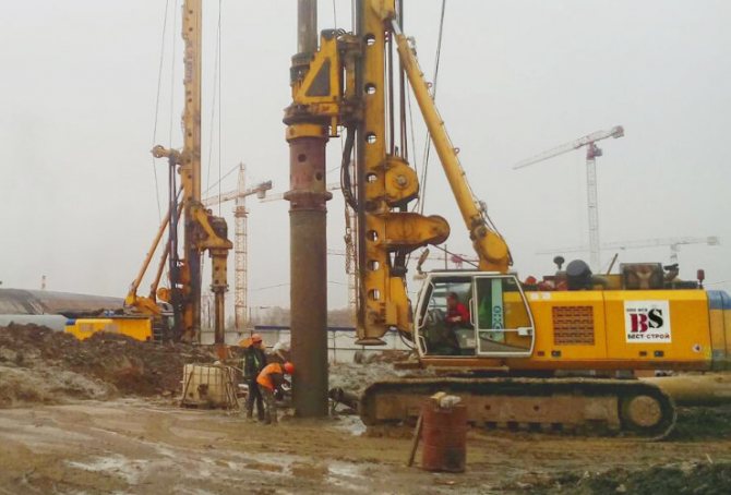
BNS device with casing pipes
The diameter of bored piles is determined by calculating the bearing capacity and can be in the range of 300-2000 mm, and the depth is also determined by the level of the load-bearing supporting layer of soil, and can reach 76 m. The purpose of bored piles is to provide a strong foundation for massive buildings and structures due to the large diameter and immersion depth, allowing to reach low-compressible bearing layers and provide a large-area support heel.
In simple soil conditions, a less expensive method of installing bored piles using a continuous hollow auger is used. The essence of the method is that concreting is carried out not using a separate concrete pipe, but directly through the cavity of the drill auger. When the drill reaches the designed depth, concrete is supplied into its cavity under pressure and as it rises, the well is filled with concrete. At the last stage, the reinforcement frame is immersed. After the concrete has set and cured, the pile is ready.
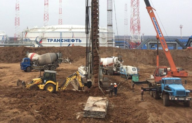
Construction of NPS piles for the foundation of an oil tank
Bored injection piles (BIS) have a special application: strengthening old, dilapidated building foundations, as well as in case of danger of subsidence and soil movement. Drilling with a diameter of 150-250 mm occurs in the immediate vicinity or through the foundation structure. In these cases, LSI reinforcement may not be performed.
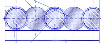
Burosecating piles are intended for constructing a solid concrete wall that can serve as a sheet piling fencing for a pit and serve as a foundation and wall for the basement of a building. They are carried out by the method of sequential drilling and concreting of first odd-numbered wells, and then even-numbered ones, ensuring their engagement.
Pile calculation
Calculation of foundation pile racks is performed:
- According to the bearing capacity of the soil under the heel of the pile,
- According to the strength of the pile structure,
- Based on existing horizontal loads.
The sequence of selection, manufacturing, deepening, quality control, testing of piles is regulated by SNiP 2.02.03-85 “Pile foundations”.
Foundations and foundations of transport structures: Electronic textbook, page 24
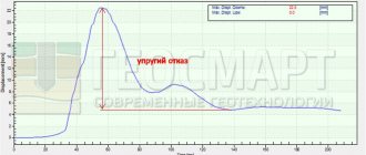
During the process of driving piles around them, the natural state of the soil changes. In water-saturated clay soils, under dynamic influence, thixotropic softening occurs, as a result of which the soil resistance to pile immersion decreases (pile failure increases). After driving the pile, during its “rest”, structural connections are restored in the surrounding soil and the load-bearing capacity of the pile gradually increases. The so-called phenomenon of pile suction is observed, and its refusal of the control blow at this time will be less than before the “rest”.
When driving piles into sandy soils, a zone of highly compacted soil is formed at its lower end, and the driving of piles slows down (the failure value decreases). During the process of “resting” the piles, the stresses in the compacted soil zone are resolved (relaxed), and the resistance to immersion of the pile decreases (failures increase). Rejection of a pile before its “rest” is called false, and after “rest” it is called true. To assess the load-bearing capacity of piles, true failure values are used. In this case, the piles after their immersion must “stand” for at least 3 days in sandy soils and at least 6 days in clayey soils.
Design value of bearing capacity of piles F d
based on the results of dynamic tests, they are determined in accordance with formula (4.8).
The dynamic method of testing piles, compared to the static one, gives less accurate results, which is explained by the different nature of the soil near the piles under dynamic influence on it during the driving process and under the action of static loads from the structure.
Only driven piles are subject to dynamic testing. Cast-in-place, drilled, and large-diameter shell piles, screw and camouflage piles are tested with static test loads.
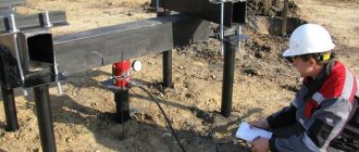
4.4.5 Load-bearing capacity of piles based on the results of static sounding of soils
Static probing is used to approximate the load-bearing capacity of driven friction piles [6, 7]. Its essence is that a special probe is pressed into the soil at a speed of no more than 0.5 m/min, which makes it possible to separately record the friction forces on its side surface and the indentation resistance of a conical tip with a diameter of 36 mm with a sharpening angle of 60°.
The partial value of the ultimate resistance of the pile at the probing point is determined by the formula:
F ui =
b1
q sA +
b2
f suh
, (4.11) where b1 and b2 are coefficients determined from the graphs in Fig.
4.23; q s
is the average value of soil resistance to indentation of the probe tip near the tip of the designed pile, obtained by dividing the indentation force of the tip by the area of its horizontal projection;
A
and
u
are the area and perimeter of the cross section of the pile;
f s
is the average value of soil resistivity to friction along the lateral surface of the soil within the limits of the pile immersion depth
h
.
The estimated load-bearing capacity based on sounding results is calculated in the same way as when testing full-scale piles, using formula (4.8).
Separation of piles according to manufacturing conditions
There are two main classifications of piles according to the conditions of their manufacture: those produced in production and in the ground. If in the first case the product is immersed in the ground in finished form, then in the second it is manufactured directly at the construction site. Such products are called bored or stuffed.
Driven piles
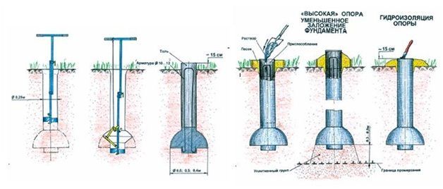
The first stage of installation of such piles is drilling a well to a certain level. Subsequently, concrete or a reinforced concrete structure is packed into it. Often, an expansion is made in the lower part of the well by drilling the soil or expanding it by intensive compaction of concrete. As a result, the pile will have an expanded heel.
Manufacturing of reinforced concrete piles in the ground
The next step is to strengthen the bed. To do this, crushed stone or slag is poured into the bottom of the well and compacted to strengthen the future pile. The maximum parameters of a bored product are up to 0.5 m in width and up to 50 m in depth.
Then a casing pipe is installed in the well, which will subsequently serve as a foundation. If the pile design requires additional reinforcement, a reinforcement frame is installed in the casing. The pipe has a loose shoe, which forms an expanded heel during the compaction of concrete.
The concrete mixture is poured into the pipe, after which the material is compacted. It is performed by hitting a pipe with a hammer or using vibration stamping technology. The second method is more economical and is being used more and more often today.
4.3. Pile foundations.
Concepts: refusal, false and true refusals.
Phenomena occurring in the soil during pile driving.
The amount of immersion of a pile upon impact (driving) is called failure.
When driving piles through sandy soils
The magnitude of failure decreases sharply with depth and in some cases can reach
zero
.
To increase pile failure, rest
, i.e. stop driving for 3...5 days. During this time, pore pressure is restored in the space around the pile, groundwater again approaches the pile shaft, friction decreases and the pile can be finished off again. the failure increases relative to the initial value obtained before rest.
The same effect can be obtained by adding water to the area around the pile during driving.
When driving piles through water-saturated clay soils
The magnitude of failure can increase with increasing driving depth and the pile seems to fall into the water-saturated base.
When driving in clayey soils, the failure value (e) either becomes constant or increases with depth.
After resting for 3...6 weeks (removal of dynamic effects), the magnitude of the failure decreases. This phenomenon is called “pile suction”.
Failure(s) of a pile during driving is called " false"
».
Pile failure(s) after rest – “ true”
.
Obtaining a true failure of a pile in clayey soils leads to an increase in its load-bearing capacity.
How much does the bearing capacity of the pile increase after resting?
IN
Almost maximum load-bearing capacity when driving
sandy loam – 1.1…1.2 times
Increased load-bearing capacity must be taken into account
conclusions
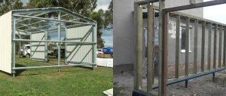
Very often you can hear that screw piles cannot support houses made of natural or artificial stone materials, especially if the structure has more than one floor. In principle, this is true, but if you perform the appropriate calculations and use reinforced piles of large cross-section, the bearing capacity of screw foundations can increase to the required limit. If not for one thing. As we said above, the entire load-bearing function of screw piles is performed by the screw blades. But will they support the foundation so well in the soil loosened during the screwing process? Most likely no.
In any case, the decision about the sufficient load-bearing capacity of screw piles should be made taking into account the climatic characteristics of the region, the amount of precipitation, the weight of the structure itself and the load-bearing capacity of the foundation.
Having studied all the disadvantages and advantages of such foundations, you can safely use screw piles where needed. By the way, online reviews of screw piles will help you better understand the disadvantages of such structures.
How is a pile foundation constructed?
A pile foundation is a supporting structure for a building, consisting of free-standing piles or a pile field. They are usually made of reinforced concrete, but it is possible to use non-reinforced concrete or rubble concrete, which somewhat reduces the cost of the structure. To increase strength and save concrete, the pile foundation is reinforced. Rods made of smooth or profiled steel are usually used as reinforcement. Foundation piles must be installed at the corners of the building, at the intersection of internal load-bearing walls with each other and with external walls. If the distance between the required piles is from 2 to 2.5 m or more, then intermediate ones are also installed between them.
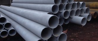
Shell piles application, materials
An effective means of creating a reliable foundation, used in large construction. They serve for a long time. They are rods of large diameter that are empty inside. Standard length is 12 m. Used in the construction of large structures.
Excellent for wet, unstable, weak soils, in the presence of seismic activity, constant vibrations, since they are in close contact with different soil layers throughout their entire length. Installation requires significant space and the use of complex technologies.
Mainly made of reinforced concrete. This allows you to increase their length to 48 meters. Extension is carried out using flange-type connections using bolts. Often supplied with cone-shaped tips. Metal shell piles are ordinary pipes with different cross-sections.
Immersed using special vibration technology. This method in some cases involves the excavation of loosened soil, but you can do without it. The use of such equipment must be coordinated with the relevant authorities, since vibration is dangerous for nearby architectural structures.
Types of piles and pile foundations
Classification is carried out by type, see section 6 SP 50-102-2003. It describes the structure of a pile foundation, its design, as well as the types of pile foundations.
According to the method of immersion they are:
- Hammered or pressed. The finished ones are immersed directly into the ground or into leader (pre-prepared) wells.
By material - concrete, reinforced concrete, steel, wood.
with non-stressed reinforcement installed longitudinally and transversely with spacer sections of reinforcement;
with prestressed longitudinal rod or rope reinforcement with or without transverse reinforcement.
According to the section configuration:
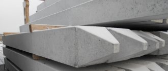
transverse - rectangular, square, round, I-beam and T-beam, round or square with a round cavity.
longitudinal - cylindrical, prismatic and with lateral inclined faces - trapezoidal, diamond-shaped, pyramidal;
by design - solid and composite;
according to the appearance of the lower end - with a flat end, with a pointed end, with a voluminous widened end - club-shaped, hollow with an open or closed end and with camouflage heels - with explosive cavities.
ready-made elements are installed on the solution;
a reinforcing frame is installed and concrete is poured.
Application of figured piles of various types
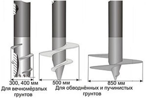
In particularly difficult conditions, for example, with severe freezing of the soil or excessive load on the soil, the use of piles with various shapes is recommended. They can be either made in the ground or driven in.
The following types of products are distinguished:
- pyramidal;
- trapezoidal;
- diamond-shaped;
- with a wide heel.
Type of piles with a widened heel
All these types of piles are used only as hanging posts, as they allow full use of the supporting capacity of the soil. The first three types of products are used in conditions of severe soil freezing to minimize tangential forces during soil heaving.
Piles with a widened heel are used in soft soils, under which denser layers lie. Such products are used as racks and can ensure the strength and reliability of the foundation even on unstable soils.
Types of pile foundations:
- From single piles. Used for individual support columns. Can be used for fences or small objects.
The foundation is a pile bush. Several supports on which the structure stands. Types of pile bush:
cluster - three piles - in a triangle, four - in a square, five - in a square with a central support, the distance between them is from 2.5 to 3.5 pile diameters;
tape - driving in one or two lines, the distance between the supports is more than three transverse dimensions (or diameters);
continuous field - piles are driven in rows and form a continuous field with distances from 3 to 6 diameters.
Differences between columnar and pile foundations of a building
The commonality is that the base is not solid, but discrete, with separate “points” of support.
Differences between pile and column foundations:
- At the depth of placement: piles are immersed to a depth of more than 5 m, pillars - slightly below the depth of soil freezing, i.e. in Russia it is from 1 to 2.5 m.
- The pillar transfers the load from the building to the ground with its sole, the pile - both with its sole and side surfaces.
- Different cross-sectional areas - the pile is long and thin, the pillar - wide and short.
- Piles can be used on soils with low load-bearing properties, for example, on water-saturated, heterogeneous soils, pillars - on dense, homogeneous soils, with a large depth of groundwater, etc.
Classification by material type
To determine what types of piles there are, you should consider in more detail their classification by type of material. The durability, reliability, and resistance to external irritants of the foundation being built will depend on its choice.
Wooden
Products are made primarily from the following types of wood:
- pine, spruce;
- oak;
- cedar;
- larch or fir.
Wooden piles are either solid or spliced along their length; in the second case, the logs are connected using metal plates.
At a lower price for wood products, it is important to consider that they can withstand less load compared to reinforced concrete or iron counterparts. Most often, wooden piles are used in the construction of temporary structures.
Reinforced concrete
This type of piles has the most common application. They can be either monolithic or prefabricated.
Monolithic structures have different sections: round, square, rectangular. Section parameters – from 20Х to 40Х40. The end immersed in the ground has a pyramidal shape. When driving the foundation, it is additionally protected by a steel shoe. A monolithic structure is almost always strengthened by internal longitudinal reinforcement. To increase the strength of the pile, it can have transverse reinforcement made of low-carbon wire.
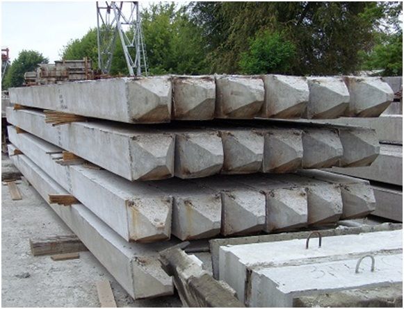
The most common type of reinforced concrete piles
Prefabricated piles are assembled from tubular reinforced concrete elements. Assembly is carried out in advance at the production site or directly at the construction site.
Driving reinforced concrete piles can be carried out using pile drivers, mobile cranes and other specialized equipment. The less expensive vibration-immersion technology has become widespread.
When driving piles, their upper surface is protected by a triple layer of metal mesh in increments of 5 cm. This measure prevents the destruction of the reinforced concrete product during the transfer of load from the hammer.
Metal
The main advantage of metal or screw piles is the ability to create point-by-point load-bearing capacity in places where the use of reinforced concrete technologies is either impossible due to difficult access or is too expensive. Today, this type of support is used more and more often in civil engineering.
The products are made from solid pipes, tapered on one side. A sheet metal flange is welded to the pipe near the tip. The following types of screw piles exist:
- welded;
- with cast tips;
- Geoscrews.
Application of metal piles
The use of metal piles is advisable in the construction of foundations on difficult soil. With their help, you can significantly save your budget, while achieving maximum quality and structural strength. Foundation construction time and noise are reduced by 2 times compared to reinforced concrete analogues.
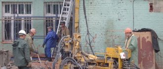
Construction of a pile foundation made of driven piles, main differences and application
A pile driven foundation can be made on any structures described in subsection 2. clause 1 of this article.
They will be named after the driven pile used.
Drivers are immersed in the ground to a depth specified by calculation in one of the following ways:
vibration driving using one of several types of vibrating hammers;
A strip or beam lattice grillage or grillage in the form of a solid slab is installed on the heads.
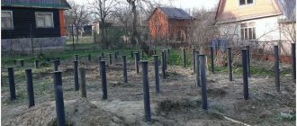
Pile classification
Using the soil immersion method:
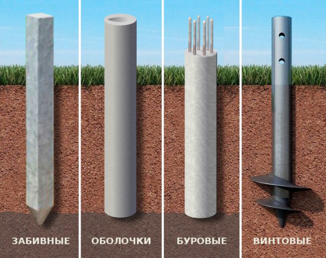
Comparative diagram of 4 types of piles
- Driven, immersed in the ground without excavating it using pile hammers, vibratory hammers, pile-pressing units.
- Shell piles are buried using vibratory hammers with soil excavation.
- Reinforced concrete drills, installed in the ground by concreting wells.
- Screw metal, screwed into the ground.
Driven reinforced concrete piles are mainly used in mass construction. In some cases, it is permissible to use wooden and metal steel driven piles.
According to the method of support on the ground:
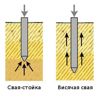
Comparison of piles by method of support on the ground
- Rack piles - rest on rocky and low-compressible layers. The load is transmitted through the heel of the pile.
- Friction piles - rest on compressible layers. The load is transmitted by the side surface and the heel.
Next, we consider the types of piles according to the type of design.
Installation of pile foundation grillage
Grillage is a lattice made of monolithic reinforced concrete connecting the heads. It is arranged to accommodate load-bearing external and internal walls.
- low or buried - the upper plane or cut is at or below the ground level, in this case it is similar to a shallow foundation, but differs from it in that it is supported not on the ground, but on piles;
- elevated or superficial - the lower plane is on the ground, but does not rest on it; on heaving soils, a sand cushion is required;
- high or raised - when heaving the soil does not reach it, it requires a back-up device - a light wall from the ground to the grillage.
The grillage design can be:
- prefabricated - finished beams are installed with their ends on driven piles, the joints are connected with cement-sand mortar;
- prefabricated monolithic - finished beams are made with reinforcement outlets, reinforcement joints are welded and concrete is poured into the formwork;
- monolithic - the reinforcement frames of the grillage beams are installed in the formwork, connected according to certain rules and filled with concrete.
For information on the rules for constructing grillages and reinforcing joints of walls and corners, see here (articles “Reinforcement of a strip foundation” and “Reinforcement of a columnar foundation”).