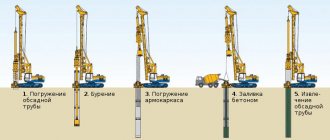
Any pile structure is installed according to preliminary calculations. You can’t just arrive at the site, mark the locations of future piles, and then immediately start driving or screwing them into the ground.
This will not ensure the reliability of the structure, because the pile rods can go as far into the ground as possible without ensuring the reliability of the foundation. In order to determine the depth of piles at which they will reach solid ground, the concept of pile failure was introduced. There are calculated and practical failures, the essence of which comes from their name.
The failure of a pile during driving is the degree to which it sinks during the driving or pressing process. In practice, this means that the pile will no longer go beyond this value, having found support on dense soil. Pile failure is measured to the nearest millimeter.
What is a pile pledge
The pledge is a series of idle blows (more than 3) with a hammer on the pile, at which the average failure is determined.
If the pile is driven with a diesel hammer, the deposit is usually considered equal to 10 blows. If double-action hammers or vibratory hammers are used when driving piles, the deposit is measured by the number of blows per unit of time (per 1 minute). In any case, the pile is driven until the design failure value is reached.
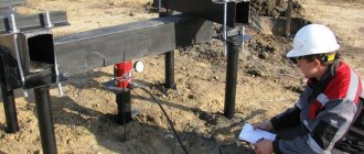
Dynamic testing of piles with determination of elastic failure
Dynamic tests with determination of elastic failure
The main advantage of measuring elastic failure during dynamic testing is a more reliable determination of the load-bearing capacity of the pile Fd. This makes it possible to more fully use the reserves of the bearing capacity of the foundation and, as a result, effectively design pile foundations. Below is a formula that determines the permissible load on a pile N. In accordance with this formula, the value of the load that can be transferred to a pile with registration of elastic failure will be 15% higher compared to a similar pile that was tested without measuring elastic failure.
ɣk is the reliability coefficient taken equal to:
1.25 - if the load-bearing capacity of the pile is determined by calculation based on the results of static sounding of the soil, according to the results of dynamic tests of the pile, carried out taking into account elastic deformations of the soil, as well as according to the results of field tests of soils with a reference pile or a probe pile;
1.4 - if the load-bearing capacity of the pile is determined by calculation, including based on the results of dynamic tests of piles performed without taking into account elastic deformations of the soil;
The process of testing dynamic tests of piles with the determination of elastic failure on video.
The figure below shows a diagram of the displacement of the pile after a single hammer blow.
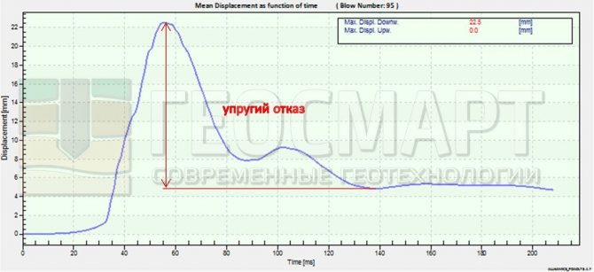
After each impact, the pile moves in three stages: first it moves to a certain maximum depth, then it is pushed up by the elastic forces of the soil and, after rapidly decaying vibrations, stops in the ground at a mark that differs from its position before the impact by a certain amount, called residual failure. The difference between the values of pile immersion to the maximum depth and residual failure is called elastic failure.
In accordance with Appendix D SP 45.13330.2012 “Earth structures, foundations and foundations”, the design failure for reinforced concrete piles over 25 meters in length, as well as steel tubular piles, should be assessed by calculation based on wave theory. Below is an example of calculating the failure of a metal pile with a closed lower end driven by driving. Geometric parameters of the pile: length 35 meters, shaft diameter 325 mm, for the development of one of the oil and gas field facilities.
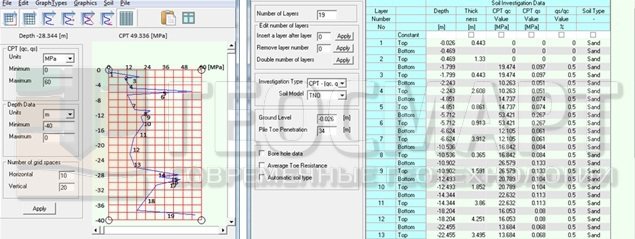
To calculate the interaction of a pile with the surrounding soil mass based on solving the wave equation, it is necessary to set the characteristics of the soil conditions of the construction site. Characteristics can be set based on static sounding data or on the basis of tabular data (a summary table of physical and mechanical properties of soils). An example of specifying soil conditions is given below.
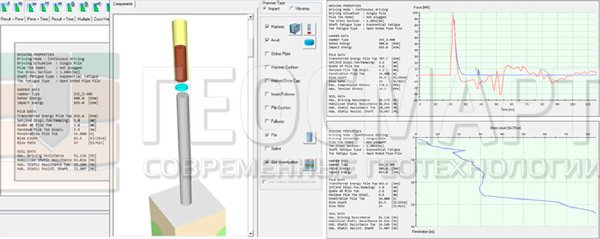
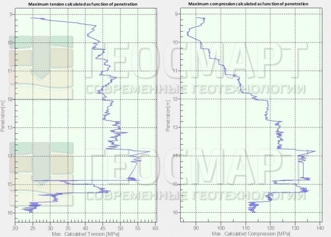
The purpose of the calculation is to select the necessary equipment for driving piles. In case of incorrect selection of pile-driving equipment when driving a pile, a “false” failure is recorded when the pile is driven with a low-power hammer. In this case, the lower ends do not reach the design marks. The small impact energy of the hammer is spent mainly on the destruction of the heads of the piles, and not on their immersion. The calculated failure obtained from the calculation results is compared with the actual failure measured during dynamic tests after the piles have rested. If the actual failure exceeds the design failure, additional static tests must be considered. When driving composite reinforced concrete piles, hydraulic hammers are usually used with the ability to change the impact energy. In this case, it is necessary to control the level of stresses that arise in the pile during their driving to prevent its destruction due to the stress exceeding the limiting strength of the pile material. Below is an example of recording compressive and tensile stresses in the body of a pile during driving (at the Leroy Merlin facility in Kemerovo).
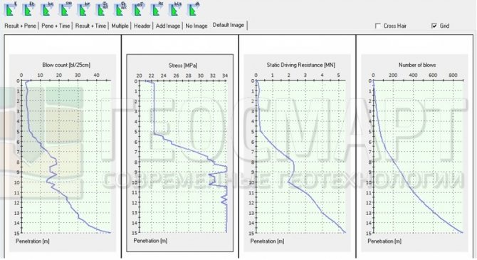
The use of automated measuring instruments allows you to obtain results in graphical form directly during the testing process. Below is a graph of the dependence of the immersion depth on the number of blows, the immersion depth on the stress level in the pile material, and the mobilization of dynamic resistance during the driving process.
Get expert advice by phone: Engineer LLC NPO Geosmart Alexander +7-908-579-39-03
We work throughout Russia and the CIS! Calculate the cost of testing
Other :
Testing piles using a more modern method in accordance with clause 8.4 of GOST 5686-2012 Stamp testing of soils (determining the deformation modulus) in accordance with GOST 20276-2012
True and false pile failure
False failure - failure during pile driving
True failure - can be obtained after rest (a period of 3-6 weeks after removing the static load on the piles).
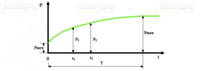
Graph of the growth of the load-bearing capacity of a pile over time in clayey soils.
- R.init – the initial load-bearing capacity of the pile at the time of driving;
- Р.max – maximum load-bearing capacity of the pile;
- T = (3...6) weeks – a period of relatively rapid increase in the load-bearing capacity of the pile;
- t1, t2 – pile testing time;
- Р1, Р2 – load-bearing capacity of the pile, respectively, at time t1 and t2.
Control during the construction of pile foundations
- Scheme of operational control during the installation of piles.
- Permissible deviations of piles.
- Requirements for the quality of piles.
- Instructions for carrying out work.
Composition of operations and controls
| Stages of work | Controlled Operations | Control (method, volume) | Documentation |
| Preparatory work | Check: | Passports (certificates), inspection report of hidden work, general work log | |
| — availability of a quality document; | Visual | ||
| — the quality of the surface and appearance of the piles, the accuracy of their geometric parameters; | Visual, measuring | ||
| — the presence of a breakdown of the pile field; | Visual | ||
| — availability of PPR for the installation of a pile foundation; | Same | ||
| — availability of an inspection certificate for previously completed earthworks; | Same | ||
| — presence of pile markings; | Same | ||
| — compliance of piling equipment with the project. | Same | ||
| Driving piles and cutting pile heads | Control: | General work log, pile driving log | |
| — accuracy of installation at the place of immersion of piles; | Measuring | ||
| - failure rate of driven piles; | Same | ||
| — amplitude of vibrations of piles at the end of vibration loading; | Same | ||
| — position in terms of driven piles; | Same | ||
| — marks of pile heads; | Same | ||
| — verticality of the axis of driven piles; | The same, 20% of piles selected at random | ||
| — dimensions of defects in pile heads. | Technical inspection, each pile | ||
| Acceptance of completed work | Check: | Certificate of inspection of hidden work, as-built geodetic diagram | |
| - actual deviations of driven piles from the alignment axes in plan and from the design elevation; | Measuring, each pile | ||
| — compliance of the location of the piles in the plan of the pile field with the project. | Visual, measuring | ||
| Control and measuring instruments : metal tape measure, plumb line, level, theodolite, tacheometer. |
| Incoming and operational control is carried out by : a foreman (foreman), a surveyor - during the work process. Acceptance control is carried out by : quality service workers, foreman (foreman), representatives of the customer’s technical supervision. |
Technical requirements and maximum deviations
SNiP 3.02.01-87 “Earth structures, foundations and foundations.”, clause 11.6, table.
18 (excerpts from the table) or
SP 45.13330.2012 “Earth structures, foundations and foundations.”, clause 12.7.5, table. 12.1 (excerpts from table)
| Technical requirements | Limit deviations | Control (method and volume) |
| 1. Installation of piles at the immersion site with diagonal or diameter dimensions, m: | Without conductor, mm | With conductor, mm | Measuring, each pile |
| up to 0.5 | ± 10 | ± 5 | |
| 0,6 — 1,0 | ± 20 | ± 10 | |
| over 1.0 | ± 30 | ± 12 |
| 2. Magnitude of failure of driven piles | Should not exceed the calculated value | Same | |||
| 3. Amplitude of oscillations at the end of vibration immersion of piles and pile-shells | Same | Same | |||
| 4. Position in plan of driven piles with a diameter or cross-sectional side up to 0.5 m inclusive: | Same | ||||
| a) single-row arrangement of piles: | |||||
| across the axis of the pile row | ±0.2d | ||||
| along the axis of the pile row | ±0.3 d | ||||
| b) bushes and strips with piles arranged in two and three rows: | |||||
| extreme piles across the axis of the pile row | ±0.2d | ||||
| the remaining piles and the outermost piles along the pile row | ±0.3 d | ||||
| c) a continuous pile field under the entire building or structure: | |||||
| extreme piles | ±0.2d | ||||
| medium piles | ±0.4d | ||||
| d) single piles | ± 5 cm | ||||
| d) column piles | ± 3 cm | ||||
| 5. Position in terms of driven, cast-in-place and bored piles with a diameter of more than 0.5 m: | Same | ||||
| a) across the row | ± 10 cm | ||||
| b) along the row with cluster arrangement of piles | ± 15 cm | ||||
| c) for single hollow round piles for columns | ± 8 cm | ||||
| 6. Position of piles located along the bridge facade: | In respect of | Axis tilt | Same | |
| at land level | at water level | |||
| a) in two rows or more | ±0.05d | ±0.1 d | 100:1 | |
| b) in one row | ±0.02d | ±0.04 d | 200:1 | |
| 7. Markings of pile heads: | Same | ||||
| a) with a monolithic grillage | ± 3 cm | ||||
| b) with a prefabricated grillage | ± 1 cm | ||||
| c) foundation without grillage with prefabricated cap | ± 5 cm | ||||
| d) column piles | – 3 cm (± 3 cm in SP) | ||||
| 8. Verticality of the axis of driven piles except rack piles | ± 2 % | Measuring, 20% of piles selected at random | |||
| 13. Continuity of the shaft of piles made by underwater concreting method | The pile shaft should not have discontinuities | Measuring, testing samples taken from cores drilled into piles or in another way |
| 14. Continuity of the trunk of hollow cast-in-place piles | The trunk should not have concrete spills with an area exceeding 100 cm2 or exposures of working reinforcement | Visual, each pile |
| 16. Requirements for pile heads, except for piles to which loads are transferred directly without a head (platform joint) | The ends should be horizontal with deviations of no more than 5°, the width of concrete chips along the perimeter of the pile should not exceed 50 mm, wedge-shaped chips at the corners should be no deeper than 35 mm and a length of at least 30 mm shorter than the embedment depth | Technical inspection, each pile |
| 17. Requirements for pile heads to which loads are transferred directly without a head (platform joint) | The ends must be horizontal with deviations of no more than 0.02, have no concrete chips around the perimeter more than 25 mm wide, or wedge-shaped corner chips to a depth of more than 15 mm | Same |
| Note: d is the diameter of a round pile or the smaller side of a rectangular one. |
Not allowed!
— immerse piles with cracks larger than 0.3 mm.
Requirements for the quality of used structures
GOST 19804-91 “Reinforced concrete piles. Technical conditions." , clause 1.3.11, table. 3
or
GOST 19804-2012 “Prefabricated reinforced concrete piles.” , clause 6.13, table. 3
| Name of deviation of the geometric parameter of the pile | Name of the geometric parameter of the pile, mm | Maximum deviations, mm |
| Deviation from linear size | The length of the prismatic (cylindrical) part of the pile with non-prestressing reinforcement at the length of the pile: |
| up to 8000 incl. | ±25 |
| St. 8000 to 16000 incl. | ±30 |
| St. 16000 | ±40 |
| The same, piles with prestressed reinforcement | ±50 |
| Size (outer diameter) of the cross section of the pile: | |
| up to 250 incl. | +15;-6 |
| St. 250 to 500 incl. | +20;-8 |
| St. 500 to 1000 incl. | +25; -10 |
| St. 1000 to 1600 incl. | +30; -12 |
| St. 1600 to 2500 incl. | +40; -15 |
| St. 2500 | +50; -16 |
| Pile wall thickness of types SP, SK and SO: | |
| up to 120 incl. | +10;-5 |
| St. 120 to 250 incl. | +25;-6 |
| Point or tip length | ±30 |
| Distance from the center of the tip or tip to the side surface of the pile | 15 |
| Distance from the center of the lifting (mounting) loop, pin, sleeve and slinging mark to the ends of the pile | ±50 (50 in the new GOST) |
| Deviation from straightness of the profile of the side faces of the prismatic part of the shaft (guides of the cylindrical surface) of the pile along the entire length, mm: | ||
| up to 8000 incl. | — | ±25 |
| St. 8000 to 16000 incl. | — | ±30 |
| St. 16000 | — | ±40 |
| Deviation from perpendicularity of the end plane: | ||
| in the head of the pile and the pile-shell | — | 0.015 side size (diameter) of the cross section of the pile |
| in the junction area of a composite pile of solid square section | — | 0.01 side size (diameter) of the cross section of the pile |
| in the junction area of the composite pile-shell | — | 0.005 side size (diameter) of the cross section of the pile |
The following are not allowed on the surface of piles:
- sinks with a diameter of 15 (20 new GOST) mm and a depth of 5 (10 new GOST) mm;
- concrete sagging more than 5 mm high;
- local concrete chips at the corners of piles with a depth of more than 10 (20 new GOST) mm and a total length of more than 50 (100 new GOST) mm per 1 m of piles;
- concrete and shell fragments at the end of the pile;
- cracks, with the exception of shrinkage cracks, more than 0.1 mm wide.
Marking
On the side surface of the pile at a distance of 50 cm from the end or at the end the following must be applied with indelible paint:
- manufacturer's trademark;
- pile brand;
- date of manufacture of the pile;
- quality control stamp;
- pile mass.
Each batch of piles must be accompanied by a quality document in the prescribed form.
Piles should be stored sorted by brand in stacks no more than 2.5 m high, in horizontal rows, with their tips pointing in one direction. Between the horizontal rows of piles, wooden spacers must be laid, located next to the lifting loops or, in the absence of loops, in places provided for gripping the piles during their transportation. The gaskets must be located vertically, one above the other, the thickness of the gaskets must be 20 mm greater than the height of the hinges.
Instructions for carrying out work
SNiP 3.02.01-87 “Earth structures, foundations and foundations.”, paragraphs. 11.5, 11.10
The magnitude of failure of driven piles or the amplitude of vibrations at the end of vibratory driving of piles should not exceed the calculated value. Pile failure at the end of driving should be measured to the nearest 0.1 cm.
Piles up to 10 m long, underloaded by more than 15% of the design depth, and piles of greater length, underloaded by more than 10% of the design depth, but having failed equal to or less than the design one, must be examined to determine the reasons making it difficult to immerse, based on in which a decision must be made on the possibility of using existing piles or driving additional ones.
In case of breakage of piles and in case of forced immersion below the design level, it is necessary, in agreement with the design organization, to build them up with monolithic reinforced concrete.
Why is pile failure necessary?
The design failure of a pile is a design value, the achievement of which indicates that the pile is capable of bearing the design load, and is driven before design calculations (to the so-called design failure rate). In order for calculations to determine the load-bearing capacity of a pile to be most accurate, the following is carried out under field testing conditions:
- static tests of piles;
- dynamic testing of piles;
- soil testing;
- testing of probes (piles);
- static probing.
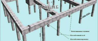
Pile failure calculation
The basis of every building is the foundation. This is where the design and construction of the entire facility begins. Nowadays, great emphasis is placed on the use of new technologies that can significantly reduce construction costs and at the same time increase the strength of the entire structure. One of these technologies is the foundation on. The essence of creating such a foundation is to drive it into the ground, thus providing a stable and durable foundation that is not afraid of ground movements.
Formulas for calculating the bearing capacity of a pile
formulas No. 18 and No. 19
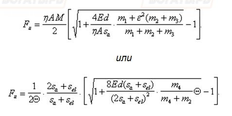
The failure calculation formula uses several parameters, in particular:
- A is the cross-sectional area of the pile;
- M is a coefficient depending on the type of soil;
- Ed is the calculated energy of vibratory hammers or hammer blows;
- m1 is the mass of the hammer or vibratory hammer;
- m2 is the mass of the pile and cap;
- m4 is the mass of the impact part of the hammer;
- Sa is the residual failure of the pile
- Sel—elastic pile failure
Hammer selection technology for driving piles
Page 2
The value of the control residual sa, m, failure when driving and finishing reinforced concrete and wooden piles up to 25 m long, depending on the impact energy Ed of the selected hammer and the load-bearing capacity of the pile Fd specified in the project, must satisfy the condition
(4)
If the actual (measured) residual failure sa < 0.002 m, then it is necessary to provide for the use of a hammer with a higher impact energy for driving the piles, at which the residual failure will be sa ³ 0.002 m, and if it is impossible to replace the piling equipment - a general control failure of the pile sa + sel , m (equal to the sum of residual and elastic failures), must satisfy the condition
(5)
In formulas (4) and (5) the following notations are used:
h is the coefficient adopted according to Table 10 depending on the pile material, kN/m2;
A is the area limited by the outer contour of the solid or hollow cross-section of the pile shaft (regardless of the presence or absence of a tip on the pile), m2;
Ed—calculated hammer impact energy, kJ, taken according to Table 11;
m1—hammer mass, t;
m2 — mass of the pile and cap, t;
m3—headstock mass, t;
e is the impact recovery coefficient taken when driving reinforced concrete piles and shell piles with impact hammers using a head with a wooden liner e2 = 0.2;
sa is the actual residual failure, equal to the value of the pile immersion from one hammer blow;
sel is the elastic failure of the pile (elastic movements of the soil and the pile), determined using a failure meter, m;
hp and hf are the coefficients of transition from dynamic (including viscous soil resistance) to static soil resistance. taken respectively equal: for the soil under the lower end of the pile hp = 0.00025 s×m/kN and for the soil on the side surface of the pile hf = 0.025 s×m/kN;
Af is the area of the lateral surface of the pile in contact with the soil, m2;
m4—mass of the impact part of the hammer, t;
g is the acceleration of gravity, taken equal to g = 9.81 m/s2;
H—actual height of fall of the hammer impact, m;
h is the height of the first rebound of the impact part of a diesel hammer, and for other types of hammers h = 0, m.
When driving piles through soil that is subject to removal as a result of subsequent excavation, or through soil for a watercourse, the design failure value should be determined based on the bearing capacity of the piles, calculated taking into account the soil that has not been removed or is subject to possible erosion, and in places where negative friction forces are likely to occur - with taking into account the latter.
Table 10 – Values of coefficient h, kN/m2, depending on the pile material.
| Types of piles | Coefficient h, kN/m2 |
| Reinforced concrete with head | 1500 |
| Wooden without headstock | 1000 |
| Wooden with headstock | 800 |
Table 11 – Estimated hammer impact energy Ed, kJ, depending on the type of hammer.
| Hammer type | Calculated energy hammer blow Ed, kJ |
| Suspended or single action | G.H. |
| Tubular diesel hammer | 0.9GH |
| Rod diesel hammer | 0.4GH |
Pages: 2