Strip foundation
In most cases, making a strip foundation with your own hands does not require a lot of work. The step-by-step instructions for performing the work ultimately determine that it is a monolithic structure, which is located along the perimeter of the entire building and under the main load-bearing walls.
Here is a brief step-by-step instruction for constructing a strip foundation:
Return to content
Marking

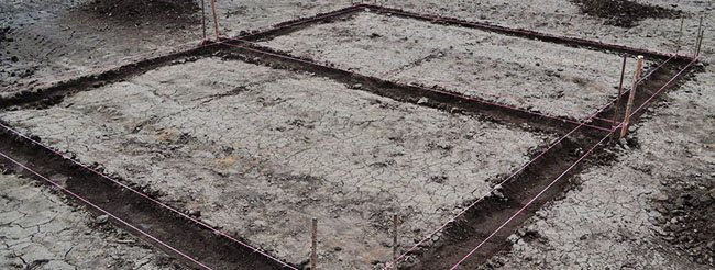
The first stage in the construction of a building on a strip foundation will be marking the future foundation of the building . To avoid various unpleasant situations during work related to the inconvenience of loading transported building materials, the access of heavy construction equipment, access to water, tools or power supply, it is necessary to correctly plan the site.
Return to content
Excavation
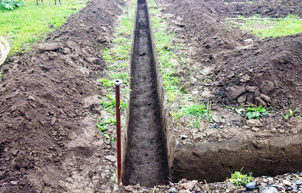
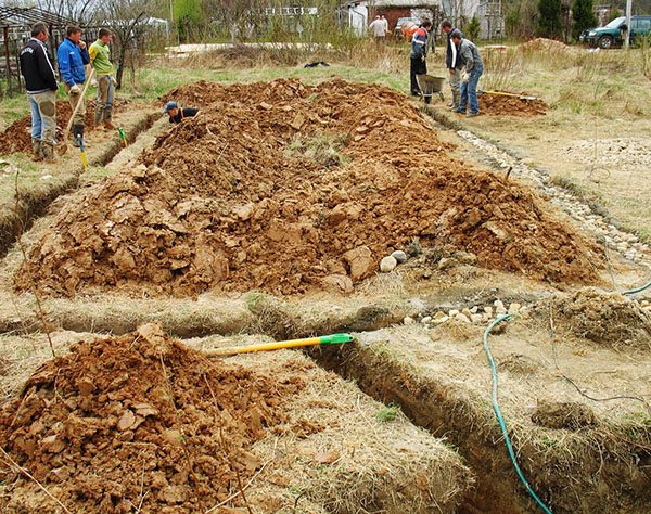
After applying the necessary markings on the ground, you need to dig a foundation pit or pit for the foundation . It should be noted that any area, no matter how flat it may be, still has a certain degree of slope. Therefore, before starting to dig various recesses for the foundation of a building, it is necessary to calculate the minimum depth of our foundation.
It will depend on what load will act on this foundation. It is worth digging from the lowest point, since it is this point that will determine the smallest depth of the foundation.
Even if you are going to do all the construction and installation work yourself, it is best to use a grader or bulldozer to level the area. This will save you from unnecessary headaches when applying markings and performing calculations.
In the case when you are interested in uneven landscapes due to design considerations, you need to determine the lowest and highest points of the future foundation , hammer stakes at these points and stretch a rope between them according to the level, which will determine the height of the future base. To simplify marking and excavation work, it is advisable to use modern measuring and technological tools:
- laser level;
- compact hand-held drilling rigs;
- tamping machines.
Return to content
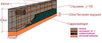
Tamping layer
After all the work regarding marking and digging holes has been completed, a so-called tamping layer is laid on the bottom of the future foundation, which can be represented by sand, gravel or any other hard material that does not shrink and compacts well .
Additional strengthening and compaction of the base of the pit is a necessary measure when constructing buildings of any complexity. This is necessary in order to impart a certain plasticity to the foundation during interseasonal fluctuations in groundwater. If you do not strengthen the bottom of the pit and do not lay a layer of sand there, there is a high probability that during the smallest shrinkage the foundation, plinth and wall of the building will crack .
The thickness of the tamping layer is on average 10-15 centimeters. After filling with sand or crushed stone, this layer must be compacted well by hand or using a special tamping machine.
Return to content
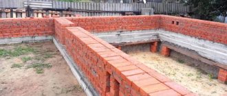
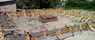
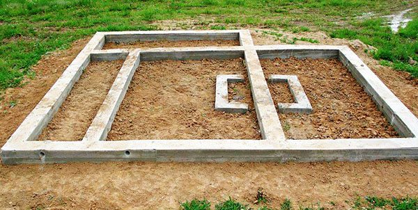
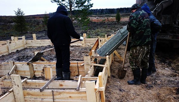
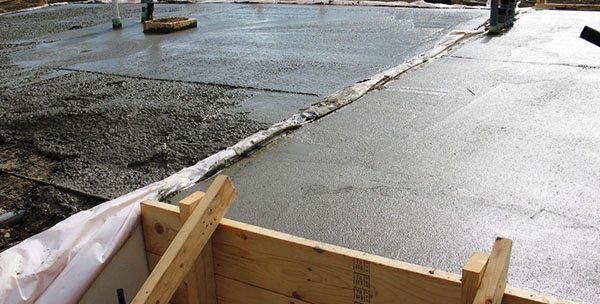
Installation of formwork
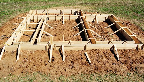
The formwork is installed clearly according to the level , since it will determine the future degree of evenness of the base. To install the formwork, you can use various materials: edged boards, particle boards, metal panels, etc. What kind of material will be used to install the formwork is not very important. The person decides for himself what material he can use, even reuse, after the foundation has already been poured.
If the outer side of the base will be decorated with any smooth materials (tiles, decorative metal, brick, natural stone), then it is advisable to use sheet materials for formwork , since they do not leave any seams after dismantling.
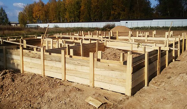
During the installation of formwork, it is necessary to take into account that the concrete solution may bend some parts of the structure . To prevent such distortion from occurring, it is necessary to install spacers on the outside of the formwork as often as possible. It must be remembered that it is advisable to knock down all the boards from the inside, bending the exposed nails from the outside. This will make the dismantling process easier and will not have such a strong impact on the appearance of the finished base.
Return to content
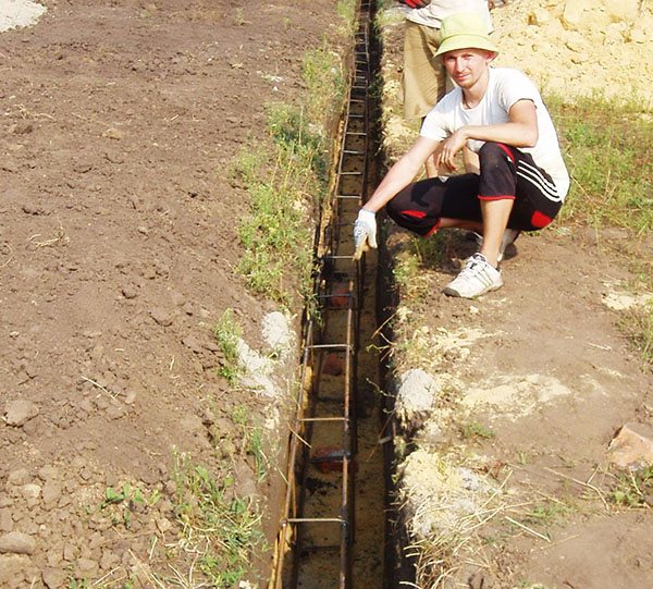
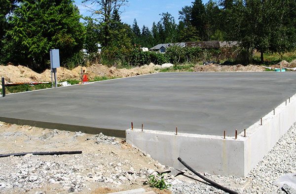
Pit reinforcement
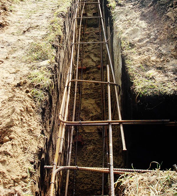
To ensure that the future foundation does not crack or sag, it is imperative to carry out reinforcement. For these purposes, reinforcement with a cross-section of 12 millimeters and special wire .
You can fasten the reinforcement together by welding, but this significantly worsens the quality of the future foundation in terms of resistance to subsidence, earthquakes, floods, etc. The edge of technological cubic cells should ideally be 30-35 cm, and the distance from the edge of the formwork should not exceed 5 cm, so that the reinforcement is inside and not outside the monolithic solution.
Return to content
Installation of technological holes
Before pouring the foundation, it is necessary to calculate all the technological openings that will ensure ventilation of the lower internal surface of the building and the laying of communications.
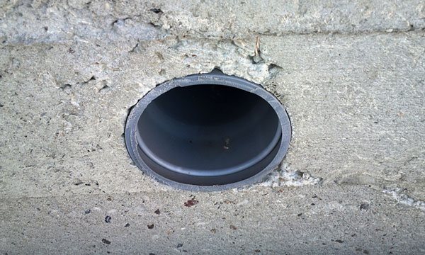
Typically, asbestos-cement or plastic pipes are used for this, which penetrate through the formwork. To prevent the solution from getting into the pipes, it is necessary to fill them with sand in advance or plug them even with any old rags that you can find by hand. It is not necessary to pull out these pipes after the poured foundation has dried, since the dense surface of their walls will prevent the destruction of these technological holes.
Return to content
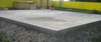
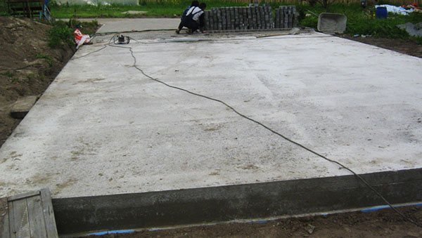
Pouring concrete
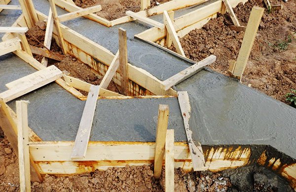
The final stage in installing the foundation is waterproofing the pit and pouring concrete mortar. To avoid the appearance of mold on the walls, chronic colds among residents of the house, the gradual destruction of the building and rotting of the load-bearing wooden elements located in its walls, it is necessary to isolate the pit from ground moisture. This can be done using roofing felt, thick construction film or more advanced materials with vapor permeability .
As for pouring concrete, it is necessary to ensure that the solution thoroughly fills all the smallest voids. To do this, you should use specialized construction equipment that can supply concrete solution at different angles.
Return to content
Modeling the impact of wind in LIRA-SAPR
In finite element modeling, the tower is represented as a spatial truss. Because Since the rigidity and mass of the structure are values independent of the external load, then when determining the natural modes and frequencies of vibrations for different pulsating loads, the case of multiple vibration modes occurs, i.e. forms with the same frequency.
If the frequency equation has multiple forms, the condition of orthogonality of the forms (along the faces of the tower, in this case along the global X and Y axes) is not valid. In this case, there is a whole family of vectors, any pair of which can serve as eigenvectors for multiple frequencies. This pair will be orthogonal to each other, but arbitrarily rotated around the vertical axis of the tower:
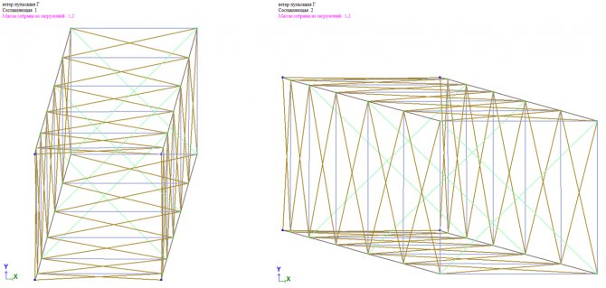
Rice. 13. Example of multiple vibration modes
Because the ordinates of vibration modes are taken into account when determining the magnitude of the pulsation component of the wind load, then in the case of multiple modes, the latter will depend on the angle of rotation of movement along multiple modes relative to the main axes of the structure. If we take into account that the angle of rotation of multiple forms is a random value, then it is difficult to predict the correctness of the results. In this case, it is possible to both reduce and increase the contribution of wind pulsation to the forces in the circuit elements.
The correct result will be obtained if the direction of movement along one of the multiple forms coincides with the direction of the wind load.
To combat multiple vibration modes, different approaches are used. The most common of them are changes in geometry (stiffness) or mass. For example, in the help for the Abaqus PC it is written:
| “In cases with repeated eigenvalues and eigenvectors, the modal summation results must be interpreted with care. You should add insignificant mass to the structure or perturb the symmetric geometry such that the eigenvalues become unique" | “In cases with repeated eigenvalues and eigenvectors, modal summation results must be interpreted with caution. You must add inessential mass to the structure or break the symmetrical geometry to make the eigenvalues unique." |
When changing the geometry, the tower is created with a rectangular cross-section with dimensions a and k*a (k is taken to be 1.01-1.05). When the masses change in one of the directions, additional masses are applied (0.01-0.05 of the total mass of the structure in this direction).
LIRA-SAPR version 2020 has a new tool: Summation of multiple forms. In the case of wind pulsation, the direction of the final vibration shape is taken in the direction of the static component of the wind load. So, when the wind is set to the edge, the total form of displacement will also be on the edge. When the wind direction is diagonal, specified through 2 components along the X and Y axes, the final direction of the form of displacement will be in the direction of the resultant, i.e. also diagonally.
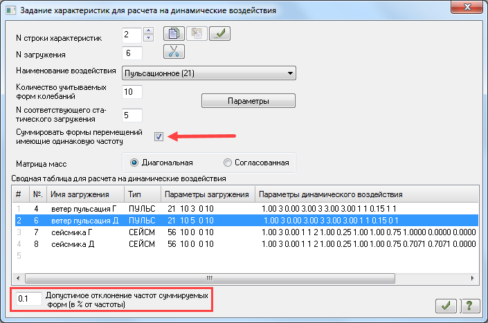
Rice. 14. Dialog for specifying characteristics for calculating dynamic impacts, version 2018
Below we will show options for calculating the tower for the action of the pulsating component of the wind load, taking into account summation over vibration modes and without it. The VAT of the scheme will be compared when determining the value of wind pulsation manually (see above) and programmatically.
Summation of multiple forms
A static component of the wind load is applied to the tower described above. The ripple component is determined by software.
The wind is on the verge.
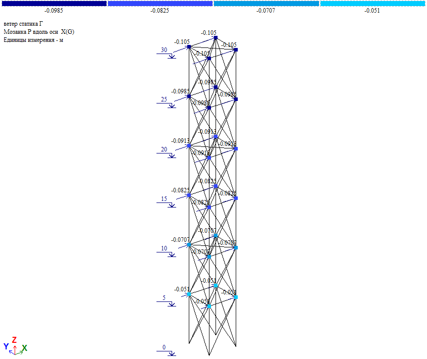
Rice. 15. Scheme of application of average wind load on the tower barrel when wind acts on the edge
The value of the nodal load is Wm/4 (Wm, see Table 2).
Pulsation component according to the calculation results:
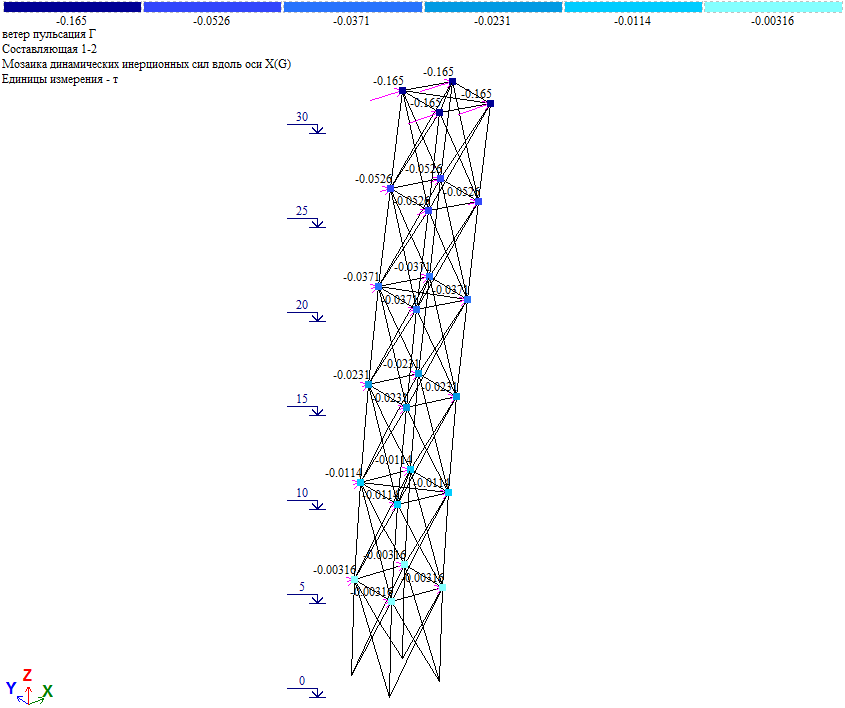
Rice. 16. Fluctuation component of wind load when wind acts on an edge
The pulsation component in the level of elev. +30.000 Wp=0.165*4=0.66tf, which is close to the load value in Table 1 (Wp=0.6575tf). Those. the results of “manual” and software calculations are the same.
Forces in the tower elements due to the full wind load on the edge (obtained via RSN):
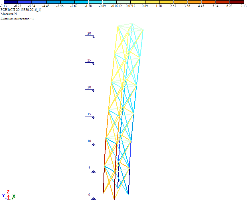
Rice. 17. Efforts in the tower elements due to the full wind load when the wind acts on the edge
As you can see, the forces coincide with the calculation result, where the tower is subject to a full wind load on the edge, determined “manually” and applied as a single load.
The wind is diagonal.
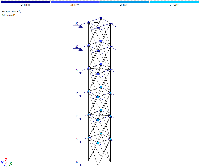
Rice. 18. Scheme of application of average wind load on the tower barrel when the wind acts diagonally
Nodal load value (Wm/4)*cos45⁰ (Wm, see table 2).
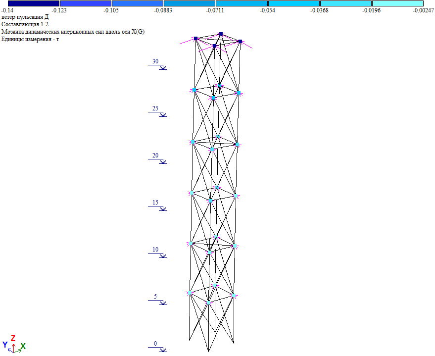
Rice. 19. Fluctuation component of wind load when wind acts on a diagonal
The pulsation component in the level of elev. +30.000 Wp=Wpx/cos45⁰=(0.14*4)/0.7071=0.792tf, which is close to the load value in Table 2 (Wp=0.789tf). Those. the results of “manual” and software calculations are the same.
Forces in the tower elements due to the full wind load on the diagonal:
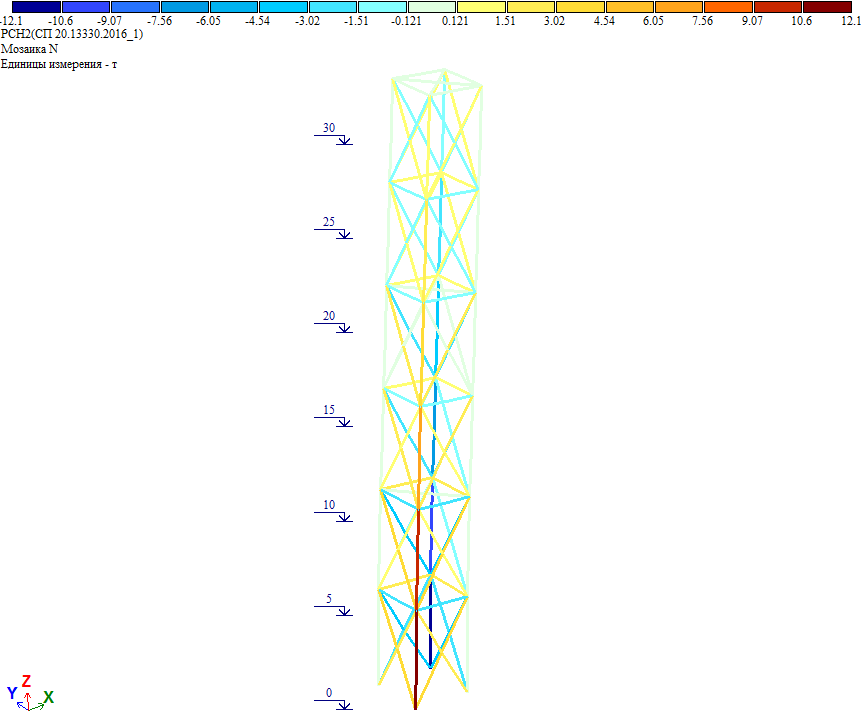
Rice. 20. Forces in tower elements due to full wind load when wind acts diagonally
As you can see, the forces coincide with the calculation result, where the full diagonal wind load is applied to the tower.
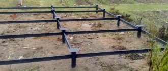
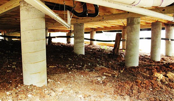
Columnar foundation
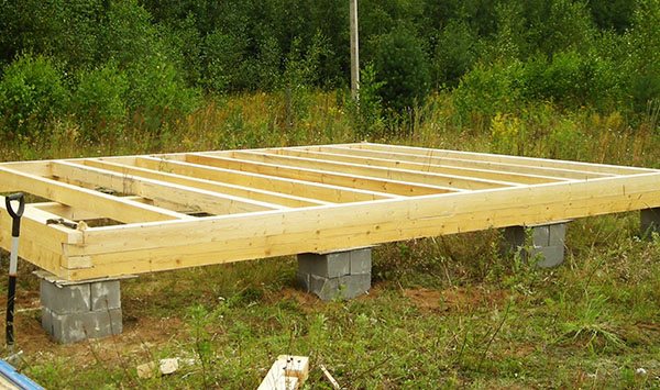
Step-by-step instructions for installing a columnar foundation are as follows:
- performing calculation work (it is necessary to clearly calculate the load of the building on the foundation and, in accordance with this, select the necessary materials, install pillars with the required frequency);
- drilling or digging holes (marking is applied and holes of a certain depth are dug for each pillar);
- laying waterproofing and a compacting layer (to compact the soil, sand or gravel 10-15 cm thick is poured onto the bottom of the pit, and a layer of waterproofing is laid);
- arrangement of pillars (a columnar foundation is installed using specific building materials, the top layer of waterproofing is laid).
As can be seen from the description, the steps for installing a columnar foundation are the same as for installing a strip foundation. The only difference is that the columnar foundation is intended for lighter type structures .
Various materials can be used as the main component for installing a columnar foundation:

- wooden poles;
- brick, stone, reinforced concrete blocks;
- asbestos-cement or iron pipes.
The installation technology will differ depending on what material is used.
Thus, when using wooden poles, special attention should be paid to waterproofing, since wood can collapse very quickly. Return to content
Example of calculating the number of pillars
The task is to calculate the foundation for a small frame house in the middle climatic zone of Russia, measuring 5 x 6 meters with a floor height of 3.0 meters and a metal tile roof. An example of calculating a columnar foundation includes several points.
- we use a foundation on round reinforced concrete pillars as a support;
- the main soil at the building site is loam (Ro – 3.5 kg/cm2);
- freezing depth 1.1 meters;
- When drilling the control pit, no groundwater was found.
Determination of weight load:
- the total area of the external walls and partitions is 76 m2 and then their total weight will be 76 x 50 = 3800 kg;
- the mass of the basement floor with an area of 30 m2 is 30 x 100 = 6000 kg, and the weight of the attic floor is 9000 kg;
- the roof area is 52 m2, which means that such a roof weighs 30 x 52 = 1560 kg;
- the snow load will be 20% of the standard with a slope of 46˚, which will be 100 x 52 x 0.2 = 1040 kg;
- the operating load on one floor is 30 x 210 = 6300 kg;
- to estimate the mass of the foundation, we take the number of pillars from a pre-compiled diagram and take their diameter to be 400 mm, then the mass of 10 pillars 1.5 meters high will be 540 kg;
- the weight of the grillage is the mass of reinforced concrete beams with a section of 400x400 m, which will be equal to 980 kg.
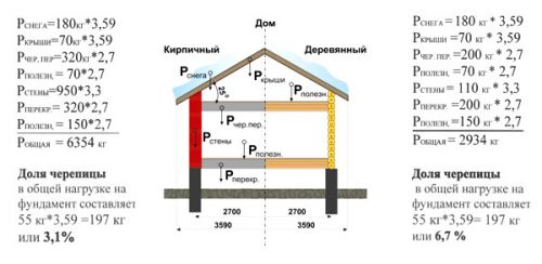
Conditional weight of a wooden and brick house.
Summing up the data obtained, we obtain the total weight of the house equal to 29110 kg. To determine the total cross-sectional area of the pillars, we divide 29110/3.5 = 8317 cm 2.
Then the cross-sectional area of each of the 10 pillars will be equal to 832 mm 2, which corresponds to a diameter of 326 mm. We take the diameter to be 400 mm and determine that for this building the minimum number of pillars required is 9 pieces.
However, taking into account the need for a strength margin of 40%, 13 pillars with a diameter of 400 mm should be accepted for installation.
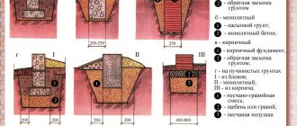
Monolithic foundation
Making a monolithic foundation with your own hands is also not particularly difficult . It is more reliable than any other type of foundation, since it is a complete monolithic reinforced concrete slab over the entire surface area of the future building. Technologically, the construction of this type of foundation is carried out in the same sequence as the installation of a strip foundation. The sequence of layers looks like this:
- priming;
- tamping layer;
- waterproofing;
- rough concrete base layer;
- another layer of waterproofing;
- monolithic reinforced concrete structure.
Despite the fact that a lot of concrete, reinforcement and sand are consumed, a monolithic foundation is the easiest to install , and the design features allow it to withstand enormous weights of several-story buildings in regions with unstable soils.
Return to content
Initial data for the calculation
In order to correctly calculate the number of supports for a columnar foundation, you need to have information. Such initial data for calculation include:
- a report on geotechnical surveys, including the structure of cross-sections of the soil and data on the occurrence of groundwater;
- soil bearing capacity;
- freezing depth and amount of snow cover in a given area, taken from SP 131.13330.2012 “Building climatology”;
- data on the specific gravity of building structures from which the building will be constructed, taken from SP 20.13330.2016 “Loads and impacts”.
If you decide not to involve specialists to carry out survey work, and you do not have information about the geology of the site, then you will need to study the soil yourself.
To do this, it is necessary to dig 2-3 holes at the building site to a depth of at least 0.5 meters below the foundation support pad. If a moisture-containing layer is discovered, then a columnar foundation cannot be used for construction. You'll have to choose a more expensive base.
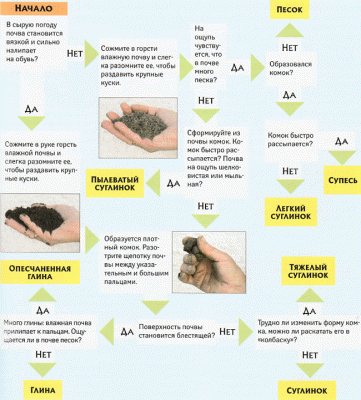
Determining the type of soil with your own hands.
Assessment of soil bearing capacity
The natural composition of the soil determines its bearing capacity and therefore, after studying the geological data, it is necessary to select from the table. 1-5 on page 6 SNiP 2.02.01-83 “Foundations of buildings and structures” data on the calculated resistance of soils corresponding to the real situation. It should be taken into account that the given numerical values refer to a depth of more than 1.5 meters. Every 500 mm rise increases this value by 1.4 times.
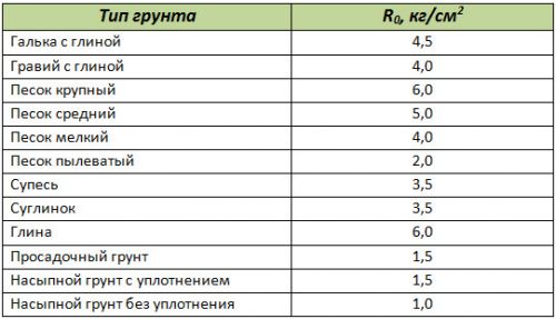
Soil resistance table (R).
Determination of weight loads on the foundation base
The weight of building structures, snow cover in winter, engineering equipment and household equipment is the most important determining factor for calculating the foundation. You can try to calculate each individual structure based on the specific gravity of its constituent elements, but this is a very large and complex task. The reference literature already provides average generalized data that can be taken as a basis. Here are some of them:
- wall made of timber with a thickness of 150 mm - 120 kg/m2;
- log walls 240 mm – 135 kg/m2;
- frame walls with insulation 150 mm thick - 50 kg/m2;
- foam concrete blocks of grade D600300 mm – 180 kg/m2;
- interfloor ceiling on wooden beams with insulation - 100 kg/m2;
- the same attic floor including insulation - 150 kg/m2;
- concrete hollow slabs - 350 kg/m2;
- operational load of floors – 200 kg/m2;
- roofing covered with metal tiles - 30 kg/m2;
- roof with slate – 50 kg/m2;
- roofing with ceramic tiles – 80 kg/m2;
- snow load for central Russia – 100 kg/m2;
- for southern regions – kg/m2.
When making calculations, you should also take into account the mass of the foundation itself. To do this, determine its volume and multiply it by the average specific gravity of reinforced concrete - 2500 kg/m2. The pitched roof angle may decrease or increase the value shown here as it changes.
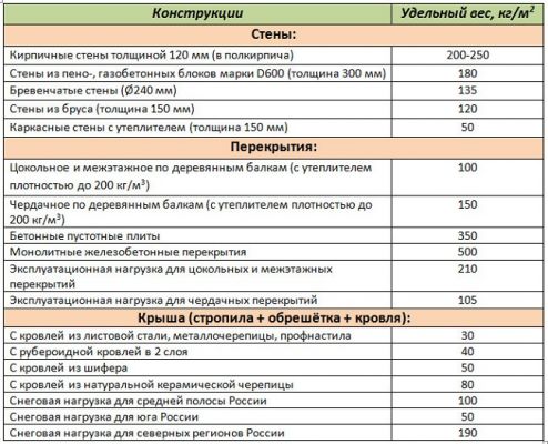
Weight of building structures.