The foundation is the supporting part of the house, which must support the weight of the entire building. The strength of the entire house as a whole depends on the strength and reliability of the foundation. Correctly carried out design of the foundation of a house can protect the building from subsidence, warping, as well as all sorts of problems associated with the appearance of cracks.
For the correct calculation and design of the foundation, characteristics such as climate, relief, and soil nature should be taken into account. For example, the foundation of a house, which is located on clay or loamy soil, is subject to serious influence from groundwater. This type of soil can erode or settle over time.
An example of a complex foundation arrangement on clay soil, which often simply needs to be done during construction
In addition, it is worth taking into account that the moisture that has managed to be absorbed into the base freezes at sub-zero temperatures, which is the reason for the formation of the so-called “swelling effect”. In most cases, this occurs in cases in which the freezing depth in the area where the foundation is being constructed is slightly below the groundwater level. As a result of all this, the foundation of the house rises in the winter, and in the summer it falls again, which entails a distortion of the entire structure.
For this reason, it is advisable to trust the construction of the foundation of a house only to professional specialists who have the necessary experience and knowledge to create a project taking into account the specifics of the soil and all climatic features.
Only professionals can accurately determine which type of foundation is best to build on a given area (ribbon, shallow, columnar). Thanks to the advice of experienced designers, you can avoid many problems and costs associated with rework and error correction.
Nuances to consider when building a foundation
When designing the foundation of a future home, you need to consider a number of points:
- When developing a pit for the foundation of a house, additional space will be required for the excavated soil. The volume of soil removed can be significant. Then it is necessary to take into account the additional costs of removing soil if its secondary use is not planned.
- The delivery and storage of materials must be planned in advance. It is advisable to place materials near the pit in descending order of its specific gravity. This will save effort when mixing and pouring concrete.
- If you plan to use machinery, then in wet weather you will need to fill the road with crushed stone or construction waste.
- When pouring concrete in several stages, it is necessary to provide additional time at the end of the shift to clean the tools from cement mortars and mixtures. Dried cement will require much more effort and time from you to clean.
- Placing bags of cement will require careful waterproofing of the site. Impermeable material must be laid on the ground and the stacks of cement must be carefully covered. Damp cement very quickly turns to stone and becomes unsuitable for use.
- The last thing you need to do is deliver the reinforcement to the construction site.
- Correctly calculate the required water supply if there is no source nearby. Make a separate point about the supply of drinking water.
- In cramped conditions, digging a foundation pit or trench begins from the most inaccessible edge.
- The easiest way to determine right angles when marking a pit is to compare the diagonals. In a regular rectangle, the diagonals should be equal.
Here in this video you can watch all the most important moments of designing a building foundation online.
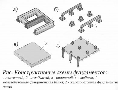
Among the main types of foundations that are used in modern construction, several types can be distinguished separately:
- tape;
- monolithic tape;
- columnar;
- pile;
- slab;
- shallow;
- screw;
- floating;
- foundation from scrap materials for small structures (bathhouse, fence, greenhouses).
Various types of foundation construction for a private residential building
Monolithic foundations of various types
For the construction of wooden houses, a monolithic foundation is best suited, which is ideal for the construction of buildings of almost any configuration.
Among monolithic bases, several types can be distinguished.
A monolithic strip foundation is a strip made of reinforced concrete that runs along the entire perimeter of the house. Used in the construction of brick buildings, houses with basements or garages, and wooden buildings.
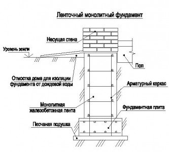
Laying drawing of a strip monolithic foundation for a house
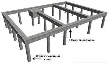
A columnar monolithic foundation is a set of pillars installed in places of increased load. Between the pillars it is planned to fill with sand or crushed stone and then fill with concrete. Such foundations are often used in the construction of light houses.
Scheme for laying a columnar monolithic foundation
A solid monolithic foundation is used in conditions of highly compressed soil and is laid under the entire area of the house.
These types of foundations are used, in most cases, in the construction of light wooden houses. Their main advantage is the absence of restrictions on the configuration of the building, as well as the need to use expensive equipment. The cost of constructing a monolithic foundation takes up about 15-20% of the total cost of the house.
Preparing the site for driving piles
It is advisable to prepare the construction site before the arrival of the pile driver. This will speed up work, ensure high output and eliminate breakdowns of expensive equipment. All this will reduce your costs. You should:
- uproot stumps and tree roots;
- remove boulders and stones;
- clear the area of debris and rubbish;
- dismantle unnecessary objects;
- cut off the top layer of soil to a depth of 10-15 cm;
- fence the area (if possible);
- arrange routes for movement of pile-driving equipment.
Pile foundation
This type of foundation can ensure the reliability of construction if work is carried out in unstable soil conditions. Used in the construction of large-sized and low-rise buildings.
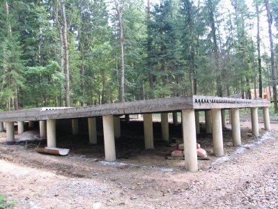
The construction of a pile foundation is, first of all, distinguished by the presence in the structure of piles - pillars that are driven or screwed into the ground using special equipment.
The depth of installation of piles directly depends on the depth of strong soil layers, which bear the entire load exerted by the building. Each of the piles individually can withstand a load of 2 to 5 tons. To connect the piles, beams attached to the top are used.
Pile foundation arrangement diagram
Pile foundations are usually used in cases where the upper soil layer is mobile or weak, as well as on soils where there are quicksand or very high groundwater levels. In most cases, pile foundations are used in the construction of large structures.
GOST 21.501−2011 “SPDS. Rules for the execution of architectural and construction working drawings"
SPDS GraphiCS - certified software
- 1 area of use
- 2. Normative references
- 3. Terms and definitions
- 4. General provisions
- 5. Architectural solutions
- 6. Design solutions
- 7. Working documentation for construction products
- Appendix A (recommended)
- Appendix B (for reference)
- Appendix B (for reference)
- Appendix D (for reference)
- Appendix D (for reference)
- Appendix E (for reference)
- Appendix G (for reference)
- Appendix I (reference)
- Appendix K (reference)
- Appendix L (for reference)
- Appendix M (for reference)
- Appendix H (for reference)
- Appendix P (for reference)
- Appendix P (for reference)
- Appendix C (for reference)
- Appendix T (for reference)
Slab foundation
This type of foundation is a monolithic reinforced concrete slab, the area of which must correspond to the area of the entire building. A slab foundation has a high cost, since its construction is accompanied by a significant amount of excavation work and high consumption of building materials. It is recommended to be used in cases where the house design does not imply the construction of a high basement floor, which will allow the foundation to additionally act as a reliable base for the floor.
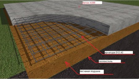
Diagram of a slab monolithic foundation for a house
For example, slab foundations are often used in the construction of frame houses.
A slab foundation, due to its high reliability, can be erected on almost any soil, including highly compressible, sandy or heaving soil. Considering that the monolithic slab runs under the entire area of the building, there is no need to worry about soil displacement. The slab base can be used in the construction of brick or wooden houses, the height of which reaches 1-2 floors.
Additional Documentation
As additional clarifying documentation, the following is attached to the general house foundation plan:
- a summary specification of all elements that are located below the zero mark (finished reinforced concrete and concrete products, metal structures, etc.).
- table of load standards,
- layout and installation plan (for prefabricated supports),
- notes and notes regarding the preparatory stage of construction, installation of hydro- and thermal insulation, design features (on separate sheets or on a general plan).
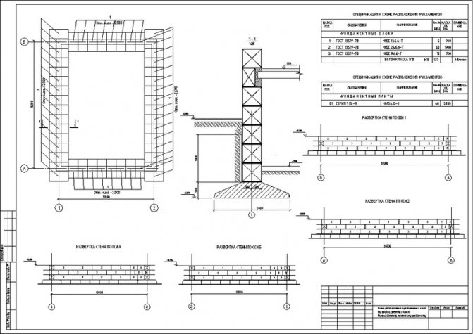
Drawing of a prefabricated strip foundation with a remote section and developments for installing blocks.
Calculation and design of foundations
The foundation design should always be carried out with full consideration of various factors, including the climatic and natural conditions of a particular area. It is worth remembering that when designing the foundation of a house, one should proceed from data on the terrain and the nature of the soil. It is for this reason that the design of any foundation begins with a careful study of engineering and geological calculations.
In this video you can see how the cost of a post foundation project for a 6x9 house is calculated.
In many regions of Russia, clayey and loamy soils predominate, the moisture in which, at low temperatures, freezes in the shortest possible time. As a result, the so-called “swelling” effect occurs, which naturally has an adverse effect on the condition of the foundation.
The same can be said in cases where the groundwater level significantly exceeds the depth of soil freezing at the construction site. This process occurs unevenly, which causes the foundation to skew and cracks to form. Bottom line: after a couple of years, the house needs renovations, which significantly increases its original cost.
Designing a strip foundation for a wooden house
When building wooden houses, you can use different types of foundations, which differ from each other in technology and laying depth. In most cases, preference is given to shallow strip foundations, since wooden buildings are relatively light in weight.
The strip foundation used in the construction of wooden houses has the necessary safety margin, and its technical and operational characteristics are fully suitable for all climatic conditions of Russia.
In addition, it is worth paying attention to the cost of such a foundation, which is noticeably lower than other types.
The foundation is based on a reinforced concrete strip reinforced in three belts, running along the entire perimeter of the future house. The foundation is laid under the walls of the first floor, both internal and external. All elements form a single system, due to which the reinforced concrete horizontal frame becomes very strong and reliable.
The thickness of the foundation is approximately 30 cm, the depth of its laying is about 80 cm, which includes a 20 cm sand cushion. The base protrudes 40 cm above the ground level. Waterproofing, which is used as roofing material, is laid under the first crown.
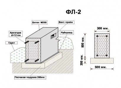
Drawing of approximate laying of strip foundation
Technology for constructing pile foundations
The technology for constructing pile foundations includes several stages:
- Drilling wells of the required diameter;
- Installation of fittings;
- Subsequent concreting of the well.
The main advantage of a pile foundation is the possibility of using a hand-held construction drill.
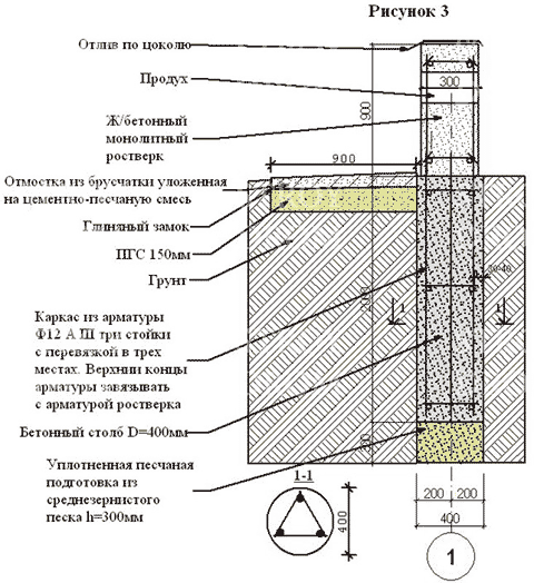
The construction of pile foundations always begins with drilling wells, the size and number of which depend on the area and weight of the future building. The parameters of the piles are determined by the loads created by the partitions, roofing and floor. Please note that the maximum diameter of a hand drill should be within 300mm. If you need to drill wells with a diameter of 600 mm, you should use an industrial drill.
At the next stage, it is necessary to carry out high-quality waterproofing of the foundation, for which roofing material is laid along the diameter of the well (a “pipe” is made from the material, which should be approximately 300 mm greater than the depth of the well). When making the upper part of the “pipe”, three layers of roofing material are used, which are pulled together using steel wire (this part will be the formwork).

Technology for laying a pile foundation for a house
If the well is a quarter filled with water, then before pouring concrete, excess liquid must be pumped out. Failure to use roofing felt can be fraught with unpleasant consequences: when the concrete sets, the cement will not gain sufficient strength, and freezing of the soil will have too negative an effect on the condition of the concrete.

Pile foundation arrangement diagram
After preparing the well, it is time to tie the reinforcement for the foundation, for which a frame is made from the reinforcement, consisting of three vertical rods with a diameter of 6 mm. The last stage is to fill the well with concrete, which must be poured in layers 40-60 cm high. During pouring, the concrete is compacted using vibrators.
6.3. Layout diagrams of structural elements
6.3.1. On the layout diagram of structural elements (hereinafter referred to as the layout diagram), structural elements and connections between them are indicated in the form of conventional or simplified graphic images.
6.3.2. The layout diagram is carried out for each group of structural elements related to the conditions and sequence of construction work.
Examples
1 Layout of foundation elements and foundation beams
2 Layout of basement wall blocks (layout of basement block walls)
3 Layout of columns, column connections, crane beams
4 Layout of trusses (beams)
5 Layout of wall panels and partitions
6.3.3. Layout diagrams are made in the form of plans, facades or sections of the corresponding structures with a simplified image of the elements.
6.3.4. The location diagram shows:
- coordination axes of the building (structure), dimensions defining the distances between them and between the extreme axes, dimensional reference of the axes or surfaces of structural elements to the coordination axes of the building (structure) or, if necessary, to other structural elements, other necessary dimensions;
— marks of the most characteristic levels of structural elements;
— positions (brands) of structural elements;
— designations of nodes and fragments;
— data on permissible installation loads.
On sections of the foundation or pile foundation of a building or structure, lines of geological sections are drawn, delimiting layers of soil with different geological characteristics.
6.3.5. Identical positions (marks) of sequentially located structural elements on the layout diagram may be applied only at the ends of the row, indicating the number of positions.
6.3.6. The layout of wall panels for a multi-tiered arrangement of panels within a floor is carried out in the plane of the walls in the view, and for a single-row arrangement - in plan.
6.3.7. In the name of the layout diagram, if necessary, information is provided that determines the position of the structure in the building (structure). It is allowed to assign serial numbers to layout diagrams.
Example - Layout of floor elements at elevation. +7,200 between axles 1
-
15, B
-
D (diagram 1)
6.3.8. Marks are placed on the layout diagram for installation in the design position of structural elements that have an asymmetrical arrangement of embedded products and other distinctive features.
6.3.9. The technical requirements for the layout provide, if necessary, instructions on the installation procedure, embedding of seams, and requirements for installation connections.
6.3.10. Examples of the layout of elements of prefabricated structures are shown in Figures L.1 - L.6 (Appendix L).
6.3.11. If a monolithic reinforced concrete structure consists of several elements (beams, slabs, etc.), for each of which separate reinforcement schemes are performed, then these elements are assigned positional designations or marks that indicate on the layout of the elements of the monolithic reinforced concrete structure in accordance with Figure 2.
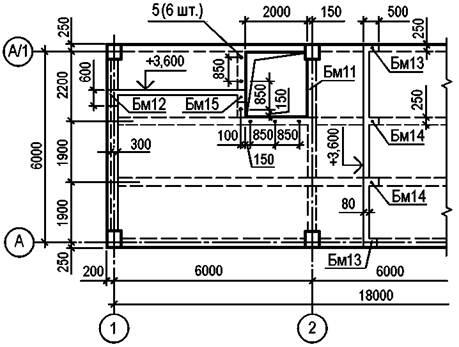
Figure 2
The layout diagram additionally indicates the formwork dimensions of the structural elements (slab thickness, girder height, cross-section of beams, columns, etc.).
6.3.12. On reinforcement diagrams for monolithic reinforced concrete structures the following is applied:
- outlines of structures - a solid thick main line;
— coordination axes of the building (structure);
- reinforcement and embedded products - with a very thick solid line (1.5 - 2 times thicker than a solid thick main line);
— positions (brands) of reinforcement and embedded products;
— dimensions that determine the position of reinforcement and embedded products, and the thickness of the protective layer of concrete;
— clamps to ensure the design position of the reinforcement (if necessary);
— instructions on the method of connecting reinforcing bars.
6.3.13. When necessary, the following simplifications are used in reinforcement diagrams:
a) frames and meshes are depicted with a contour in accordance with Figure 3;
b) to ensure correct installation of asymmetrical frames and meshes in the design position, only their characteristic features (diameter of rods of different diameters, etc.) are indicated in accordance with Figure 4;
Figure 3
Figure 4
c) if a reinforced concrete structure has several sections with evenly spaced identical frames or meshes, then their contours are drawn on one of the sections, indicating the position numbers and, in brackets, the number of products for this position. In the remaining areas, only positions are indicated and in brackets - the number of products of this position in accordance with Figure 5;
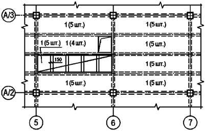
Figure 5
d) in areas with separate rods located at equal distances, one rod is depicted indicating its position on the leader line flange, and under the leader line flange - the pitch of the rods in accordance with Figure 6.
Figure 6
Note - Distribution fittings (position 6) should be laid within positions 1 and 2 at the top, within positions 3 - 5 at the bottom.
If the pitch of the rods is not standardized, then next to the designation of the rods the number of rods is indicated in parentheses in accordance with Figure 7;
Figure 7
Figure 8
e) when depicting a frame or mesh, identical rods located at equal distances are applied only at the ends of the frame or mesh, as well as in places where the pitch of the rods changes. In this case, under the flange, leader lines indicating the position of the rod indicate their pitch in accordance with Figure 8;
f) the reinforcement of elements crossing the depicted element is usually not indicated (see Figure 9);
Figure 9
g) in a complex reinforcement scheme, it is allowed to indicate positions at both ends of the same reinforcement product or a separate rod in accordance with Figure 9;
Figure 10
i) the dimensions of the bent rods are indicated along the outer edges, and the dimensions of the clamps are indicated along the inner edges in accordance with Figure 10.
6.3.14. Working drawings of reinforcement and embedded products developed for monolithic reinforced concrete structures as independent documents are not included in the main set of working drawings, but are recorded in the “Attached Documents” section of the list of reference and attached documents.
6.3.15. It is allowed not to make drawings for simple parts directly included in the monolithic reinforced concrete structure, but to provide all the necessary data for their manufacture in the specifications and, if necessary, place images of these parts on the drawing of the monolithic structure. If there is a large number of parts, the data necessary for their manufacture is given in statements in Form 6 (Appendix A).
An example of filling out the statement is shown in Figure M.1 (Appendix M).