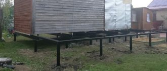
Mechanical strengthening
The mechanical method of strengthening involves introducing high-strength piles or special materials such as crushed stone into the soil. During the work, tamping or vibration can be used to compact the layers without changing their structure.
When using reinforced concrete piles, the product is passed through several layers of soil and reaches a dense layer. As a result, the load is transmitted vertically through the product. The following technologies for entering structures exist:
- Driven - piles are driven with pre-drilling or without such work;
- bored - liquid cement mortar is fed into a special pipe, after which the piles are inserted using a jacking machine;
- ground - holes are prepared by drilling, granulometric filler is poured into them and layer-by-layer compaction is carried out.
The use of bored piles requires expensive equipment and a sufficient area of the construction site. The use of soil technologies guarantees results comparable to reinforced concrete structures, but is considered cheaper and more environmentally friendly.
Methods of forming a soil cushion, achieving compaction through compaction, vibration or replacing soil are appropriate when the layer thickness is small. Density can be increased using smooth or pad rollers, vibrating plates and other types of equipment. Areas with dusty sand layers are compacted along with water. This technology is optimal for the construction of large surfaces, airfield runways and other structures that cover large areas.
Methods for strengthening foundation soils
Chernozem, peat mixtures, manure and sand - sale of soil to increase the fertility of the soil.
Strengthening soils at the base of foundations consists of the following main methods, which are currently widely used in the reconstruction of buildings and structures.
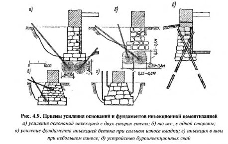
Injection with strengthening solutions. Strengthening soils using cement injections on each side of the foundation (see Fig. 4.8) and soil cementation (cementation in the presence of coarse-grained rocks, two-solution sequential silicization for fastening medium and fine sands, single-solution silicization for loess and loams, tarring of sands, clayization of loess; electrosilicatization of clays and loams.
Strengthening the base using the listed types of injections is carried out by forming separate reinforced volumes of soil with an approximate radius of up to 0.8 m.
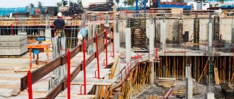
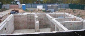
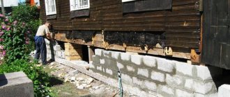
Situations often arise when it is necessary to strengthen or reconstruct the foundation of an existing building. Such situations arise when the foundation body is in poor condition, local decompaction of foundation soils due to the influence of groundwater (if the waterproofing was carried out unsatisfactorily). In this case, various methods of cementing foundation soils are used. Cementation of the foundation soil is also required when the rear ones are being built on: the load on the foundation can increase significantly, after which subsidence occurs (this is a common phenomenon, since the design load is calculated when laying the foundation). If construction of a new one begins next to an existing building, then decompaction of the foundation soils may occur. This is especially evident when excavation of a pit or drilling is carried out incorrectly and horizontal vibration occurs. In this case, it is also necessary to cement the soil of the foundation of the existing building.
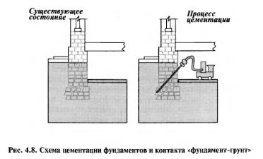
In general, cementation is carried out in two different options. The first is the cementation of the foundation itself. When implementing this method, a hardening solution is introduced into the body of the foundation and its base (special wells are first drilled in the foundation). In this case, the voids at the base of the foundation are filled with durable material that protects the masonry from destruction. This method is also called injection cementation (see Fig. 4.9).
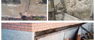
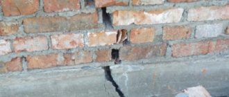
One of the main types of damage to masonry is cracks. Damage that weakens masonry includes many types of masonry delamination and loss of adhesion between the masonry material and fastening mortars. These damages lend themselves well to reconstruction and do not require soil stabilization. In other cases, not only the foundation itself, but also the foundation soils may not be able to withstand the increased load. Then soil strengthening is carried out by introducing drilled injection piles. As a result of these works, reinforced concrete piles are obtained, which at one end rest against the foundation, and at the other end against stable foundation soils (see Fig. 4.10).
The method of drilled injection piles differs from conventional cementation of foundation soils in the location of the wells. With conventional cementation, wells are located along a rectangular grid, with gradually closer spacing. Fixing the foundation soils with drilled injection piles can significantly reduce the number of wells: they are drilled only directly under the karst layers. It should be noted right away that cementing foundation soils using drilled injection piles is a rather expensive method, but at the same time it allows you to achieve the desired result for a long period.
In most cases, in the absence of other (unforeseen) damaging effects, the result of cementation of foundation soils persists for fifty years. Typically, unintended conditions refer to the occurrence of vibration. The reason for the appearance of horizontal vibration may be the construction of a new building next to an existing one or the installation of additional underground communications. Horizontal vibration causes deformation not only of the foundation of an existing building, but also of the foundation soils. Recent comparative tests of various methods of cementing foundation soils have shown that the use of drilled injection piles, despite the relative high cost of this method, makes it possible to halve the material consumption and labor intensity of work on fixing karst layers, which in turn significantly reduces the design cost of the building.
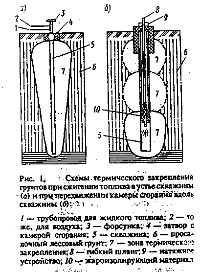
2. The thermal method, which consists in burning fuel in wells and thus creating strong soil columns, which are like a transitional structure from the bases to the foundations. It is used in forest, forest-like and clayey soils.
3. Installation of drilled injection root piles for simultaneous strengthening of foundations and lower sections of walls. This method uses cast-in-place piles with a diameter of 89 to 280 mm and a length of several to tens of meters (approximately 7-40 m). To form such piles, holes are pre-drilled with drill bits. Reinforcement with a diameter of approximately 12-16 mm can be placed in the hole. Concreting is carried out under pressure of 3-6 atm. through pipes with a diameter of 18–60 mm
In unstable soils, casing pipes are used, which in particularly difficult cases cannot be removed back. The distances between the piles range from 3 to 5 of their diameters.
An original design for strengthening foundations, and at the same time foundations and even lower sections of walls, is the installation of drilled root-shaped piles (Fig. 4.9, e). They are cast-in-place piles with a diameter of 89 to 280 mm and a length of several to tens of meters (approximately 7-40 m). To form such piles, holes are pre-drilled with drill bits. The hole can accommodate reinforcement with a diameter of approximately 12.16 mm. Concreting is carried out under pressure of 3-6 atm. through pipes with a diameter of 18–60 mm. In unstable soils, casing pipes are used, which in particularly difficult cases cannot be removed back. The distances between the piles range from 3 to 5 their diameters.
A lot of methods and designs for strengthening foundations have been developed. These include techniques similar to those used to strengthen bases, i.e. injections of various solutions. Injections are made with a cement mortar of compositions from I: 10 to 1: 1 under a pressure of 2 to 10 atm.
If the condition of the foundation material is very poor, the solution is injected directly into the destroyed stones, especially in cases where the masonry was made of small stones (Fig. 4.9c). In slightly better condition and larger stones, when only the seams and joints of the masonry are destroyed, the injection is made in these places, between the stones (Fig. 4.9, d).
If only the outer layer of the foundation masonry is destroyed, it can be strengthened by gunning the surface of the masonry with cement mortar to create a protective layer
More complex structural changes to foundations are made mainly to strengthen them when the payload in the building increases. Such structures are shown in Fig. 4.11. There are ways to widen the base of the foundation, strengthen the existing foundation structure, and even transfer pressure from the foundation to the outriggers.
In Fig. 4.11a shows the expansion of the foundation base by replacing the lower rows of masonry with concrete. In Fig. 4.11.6 shows an increase in the width of the foundation with simultaneous strengthening of its structure by concrete coating it to its entire height. At the same time, the connection of the concrete layer is ensured by reinforcement steel rods driven into the joints of the masonry with a diameter of about 20 mm. Figure 4.11c shows a method of strengthening the foundation and increasing the base of the base in the form of a reinforced concrete cage by making horizontal holes in the masonry and connecting the cages on each side with reinforcing bars located at distances of one to one and a half widths of the base of the foundation.
In Fig. 4.11d shows the strengthening of the foundation with an increase in its base by installing a concrete cage and transferring the load to it using transverse metal or reinforced concrete beams and reinforcing bars in the lower part of the foundation masonry. The distance between the beams can be approximately taken equal to their height from the base of the base.
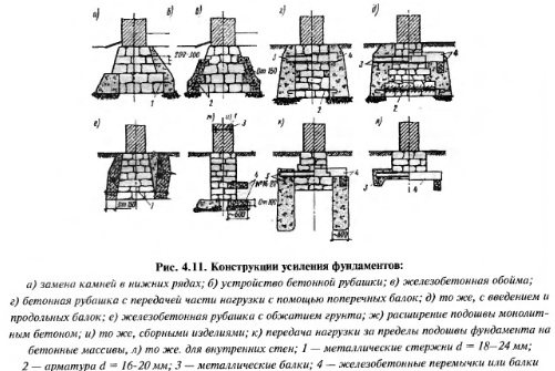
In Fig. 4.11d shows the same design, but with the introduction of additional longitudinal beams, which makes it possible to increase the distance between the transverse beams to 3-4 m or more. In the diagram Fig. 4.11f shows a solution consisting in the fact that reinforced concrete cages that have gained strength, connected at the bottom by metal rods, are pressed out with jacks. As a result, the metal rods are tensioned, the width of the sole increases and the soil is compressed.
In Fig. 4.11, g, and shows ways to increase the width and load-bearing capacity of the foundation by installing cantilever slabs made of monolithic reinforced concrete or prefabricated slabs with their location under the sole or slightly above it. At the same time, it may be necessary to strengthen the wall with metal fasteners.
In Fig. 4.11,k,l shows structures with the help of which the load is transferred beyond the base of the foundation in external walls with a deep foundation and in internal load-bearing walls.
It should be taken into account, however, that after the installation of the last two structures, settlement of the newly constructed external parts of the foundation may occur, which will lead to dangerous deformations in the walls. Therefore, this type of design cannot be recommended.
Replacement of individual sections of the foundation is carried out in small sections, up to 2 m in length, in a strictly defined sequence. During work, an unaffected part of the length of the foundation must be preserved, extending at least two sections that have already been replaced.
Features of cementation
The technology of removing soil and changing its properties is used when it is possible to remove a layer and replace it with a more durable one. Improving the quality is achieved by adding a solution based on cement and sand, which can be supplied by jet or mechanical means. In the second option, mixing is carried out by a special design of an auger drill, which assumes the presence of a rod that is hollow inside and has holes along its entire length. They serve to supply cement mixture, which is mixed with soil layers during operation of the equipment. The advantage of the method is:
- low cost;
- guarantee of results;
- suitability for wet soil;
- Possibility of use when space is limited.
Cementation can be used to strengthen the soil on which buildings are already built. For these purposes, special compact “jet piles” installations are used, which allow entry vertically and at an angle.
I. SCOPE OF APPLICATION
I. SCOPE OF APPLICATION
1.1. A standard technological map (hereinafter referred to as TTK) is a complex organizational and technological document developed on the basis of methods of scientific organization of labor for performing a technological process and defining the composition of production operations using the most modern means of mechanization and methods of performing work using a specific technology. TTK is intended for use in the development of Projects for the organization of major repairs, Projects for the production of repair and construction works and other organizational and technological documentation by construction departments. The TTK is an integral part of the Work Performance Projects (hereinafter referred to as the WPR) and is used as part of the WPR in accordance with MDS 12-81.2007.
1.2. This TTK provides instructions on the organization and technology of work on artificial consolidation of soils using the cementation method.
The composition of production operations, requirements for quality control and acceptance of work, planned labor intensity of work, labor, production and material resources, industrial safety and labor protection measures have been determined.
1.3. The regulatory basis for the development of a technological map is:
– standard drawings;
– building codes and regulations (SNiP, SN, SP);
– factory instructions and technical conditions (TU);
– norms and prices for construction and installation work (GESN-2001 ENiR);
– production standards for material consumption (NPRM);
– local progressive norms and prices, norms of labor costs, norms of consumption of material and technical resources.
1.4. The purpose of creating the TTK is to describe solutions for the organization and technology of construction and installation work on artificial consolidation of soils using the cementation method, in order to ensure their high quality, as well as:
– reducing the cost of work;
– reduction of construction duration;
– ensuring the safety of work performed;
– organizing rhythmic work;
– rational use of labor resources and machines;
– unification of technological solutions.
1.5. On the basis of the TTK, Working Technological Maps (RTK) are being developed for the performance of certain types of work (SNiP 3.01.01-85 * “Organization of construction production”) for the artificial consolidation of soils by cementation.
The design features of their implementation are decided in each specific case by the Working Design. The composition and degree of detail of materials developed in the RTK are established by the relevant contracting construction organization, based on the specifics and volume of work performed.
The RTK is reviewed and approved as part of the PPR by the head of the General Contracting Construction Organization.
1.6. The TTK can be tied to a specific facility and construction conditions. This process consists of clarifying the scope of work, means of mechanization, and the need for labor and material and technical resources.
The procedure for linking the TTC to local conditions:
– consideration of map materials and selection of the desired option;
– checking the compliance of the initial data (amount of work, time standards, brands and types of mechanisms, building materials used, composition of the worker group) with the accepted option;
– adjustment of the scope of work in accordance with the chosen option for the production of work and a specific design solution;
– recalculation of calculations, technical and economic indicators, requirements for machines, mechanisms, tools and material and technical resources in relation to the chosen option;
– design of the graphic part with specific reference to mechanisms, equipment and devices in accordance with their actual dimensions.
1.7. A standard flow chart has been developed for engineering and technical workers (work foreman, foremen, foremen) and workers performing work in the third temperature zone, in order to familiarize (train) them with the rules for carrying out work on artificial consolidation of soils using the cementation method, using the most modern means of mechanization, progressive designs and methods of performing work.
The technological map has been developed for the following scope of work:
– fixed soil – 150.0 m
.
Materials for changing properties
Today, various materials are used for stabilization, the selection of which is based on an assessment of the condition of the soil. The technology may involve the use of the following components:
- sand;
- crushed stone;
- gravel;
- clay.
Reducing the stickiness of clayey soil is often achieved by liming. The method is used in the preparation of road surfaces, as it makes it possible to increase their resistance to soaking. Changing the properties of soil can be achieved by using organic components with astringent properties. For these purposes, resin, bitumen and special emulsions are often used. The disadvantage of this method is the high cost of materials and their negative impact on the environment, so it is used quite rarely today.
Dehumidification technology
Often the weakness of the soil is due to excessive water content, the removal of which leads to an increase in the density of the layers. Changing the properties can be achieved thermally or by firing. The technology involves immersing a pipe into a well through which heated air is supplied. As a result, excess moisture evaporates, and in clay-type soils a baking effect is observed. To heat the structure, various types of materials are used:
- coal;
- chopped firewood;
- chemicals.
To dehydrate layers, an electrical method is often used, in which the movement of water towards the “minus” is observed. Electroosmosis is often used to organize foundation drainage, but this method requires significant energy consumption.
II. GENERAL PROVISIONS
2.1. The technological map has been developed for a set of works on artificial consolidation of soils using the cementation method.
2.2. Work on artificial consolidation of soils using the cementation method is carried out by a mechanized team in one shift, the duration of working hours during the shift is:
2.3. The work sequentially performed during the artificial consolidation of soils using the cementation method includes the following work processes and technological operations:
– geodetic breakdown of the location of driving injectors;
– driving injectors into the ground;
– connection of hoses for injection of solution;
– injection of solution into the soil;
– removal of injectors;
– liquidation of used wells.
2.4. The technological map provides for the work to be carried out by a complex mechanized unit consisting of: a mobile compressor from Atlas Copco XAS 97 Dd
(
compressed air supply 5.3 m / hour, = 0.7 MPa, m = 940 kg);
jackhammer Atlas Copco TEX 09 PS 8461021102
(weight m=9.6 kg, =0.5 MPa, impact frequency 1800 beats/min);
electric grinder PWS 750-125 from Bosch
(P=1.9 kg; N=750 W);
manual injection gas burner R2A-01 with
internal and external mouthpieces, key, O-rings, gas cylinders and reducers;
pipe cutting head REMS Eva;
diesel
mortar pump Putzmeister M 740
(capacity up to 5 m3/hour, =7 bar; total weight m=1450 kg; overall dimensions L W H, 4500 1450 1200 mm).
Fig.1. Injector gas burner P2A-01
a – burner; b – injection device; 1 – mouthpiece; 2 – mouthpiece nipple; 3 – tip; 4 – tubular mouthpiece; 5 – mixing chamber; 6 – rubber ring; 7 – injector; 8 – union nut; 9 – acetylene valve; 10 – fitting; 11 – union nut; 12 – hose nipple; 13 – tube; 14 – handle; 15 – stuffing box; 16 – oxygen valve.
Fig.2. Gas cylinders and reducers
a – oxygen cylinder, volume 6 m3; b – acetylene cylinder, volume 5.32 m; g – oxygen reducer; d – acetylene reducer.
Fig.3. Compressor Atlas Copco XAS 97 Dd
Fig.4. Hammer Atlas Copco TEX 09 PS
Fig.5. Mortar pump Putzmeister M 740
Fig.6. Pipe cutting head REMS Eva
Fig.7. Electric grinder PWS 750-125
Strengthening options
To strengthen the soil in coastal areas, when creating landscape design and forming slopes, the reinforcement method is often used today. It can be used on flat and sloping areas, and the holding strength is ensured by polymer structures. The following materials are often used:
- geogrid – retains movement in all planes, involves filling the honeycombs with soil or fine aggregate, which is compacted with water;
- geotextile – a multilayer fabric made of polymer materials that allows water to pass through, does not allow layers with different structures to mix and evenly distributes the load;
- geogrid - capable of absorbing tensile loads, mainly used with other materials.
A decorative option for strengthening is to sow the area with grass. It helps prevent soil shedding on slopes whose steepness does not exceed 1:1.5. The technology makes it possible to reduce the consequences of soil erosion and erosion; it also helps create fertile layers for growing crops.
Today there are quite a few ways in which it is possible to strengthen the soil. The choice depends on the characteristics of the territory and the available opportunities.
Thermal fixation of loess
Hot gases are used to complete the task. For this reason, the rock to be reinforced must have high gas permeability. Soils are fired using two methods:
- under separate building foundations (pillars, piles);
- the whole area under the house.
In both options, wells are used for heat treatment, into which a combustion chamber for fuel (diesel oil, flammable gas) is placed. In the second case, the wells are placed so that the boundaries of the hardening zones touch.
Fuel can be burned only at the top of the well or alternately along its entire height. It all depends on the available equipment. In the second case, it should allow the combustion chamber to be moved.
Schemes for thermal consolidation of soils.
The processing temperature of loess should not exceed 750-850°C. Otherwise, the rock will become impermeable to gases. The average duration of exposure to high temperatures is 5-12 days. As a result of the measures taken, the structure of the base is compacted, and strong structural bonds appear that are resistant to moisture.